
Installation

JUNO IC20LED (06LM, 09LM, 14LM) & IC22LED (06LM, 09LM, 14LM)
NEW CONSTRUCTION RECESSED HOUSINGS
Step 1. Provide electrical service according to
your local electrical code to the wiring box located
on the plaster frame. Supply wire insulation must
be rated for at least 90°C.
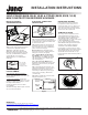
Step 2. Remove wiring box cover. Remove the
appropriate knock-out(s) to accommodate the
type of electrical service to be used/allowed by
your local electrical code (Fig. 8):
Metal Conduit. Remove appropriate round
knock-out(s) and connect conduit to wiring box
with proper connectors (not supplied).
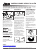
12/2 or 14/2 Non-Metallic Sheathed Cable
(Type NM-B). Remove appropriate D-shaped
cable knock-out(s). Insert NM-B cable through
cable trap and make a 90˚L-shaped bend in
cable as shown (Fig. 9).
12/3 or 14/3 Cable (Type NM-B). Remove
appropriate round knockouts and connect cable
with proper electrical connectors (not supplied
and not shown).
Step 3. Strip supply wire 3/8” and insert each
supply wire into appropriate connector. Connect
black fixture wire to hot, white fixture wire to
neutral and green fixture wire to ground. (Fig. 8).
Connect violet (+) and gray (-) dimmer wires,
( -U models only).
Step 4. Place all wiring and connectors back in
wiring box and replace cover.
Figure 7
* Note: Cut 5-5/8”
(for 5” housings)
or 6-7/8” (for 6”
housings) opening.
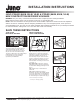
DRIVER REPLACEMENT
Driver replacements must be performed
by a qualified electrician. Remove inner
housing from fixture to access driver (Fig. 6).
Order replacement kits as identified on the
driver. The replacement kits include detailed
instructions for driver replacement.
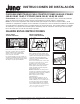
TRIM INSTALLATION
After ceiling is finished and painted, remove
paint shield from fixture. Discard or recycle.
To install trims using COIL SPRINGS remove
OPTIC REFLECTOR by rotating 1/4 turn
counter-clockwise (Fig. 10). Connect trim springs
to fixture L-BRACKETS as shown
(Fig. 11). Take note of flange details at top of
OPTIC REFLECTOR, align and insert in fixture
and rotate 1/4 turn clockwise until it stops.
To install trims with TORSION SPRINGS:
For lensed trims, it is not necessary to remove
OPTIC REFLECTOR. For lensed trims equipped
with an internal reflector, remove the reflector
supplied with the trim and discard or recycle.
For hyperbolic trims, follow instructions provided
with the trim.
FIXTURE DIMMING
Universal Voltage (MVOLT) Downlights:
Universal input voltage (120VAC thru 277VAC)
housings. Dimmable with the use of most 0-10V
wall box dimmers.
120VAC (120) Downlights: 120VAC input
voltage housings. Dimmable with the use of most
incandescent, magnetic low voltage or electronic
low voltage* wall box dimmers.
Consult Juno Product Services or website
for compatibility.
*Electronic low voltage dimmers require a neutral
wire connection in the wall box.
Figure 11
L-Bracket
Coil
Spring
Step 1. Locate center of proposed opening on
ceiling tile and cut appropriate sized hole.*
Step 2. Place ceiling tile in T-bar grid.
Step 3. Place fixture into position and snap
bar hanger foot with integral T-bar notch onto
T-bars (Fig. 6). Additional holes provided for
securing with wire or screws (Fig. 7).
Step 4. Follow Steps 1-4 under Electrical
Connection.
Figure 9
NM-B Cable
Knock-out
(D-Shaped)
NM-B Cable
Trap
(4 Places)
NM-B Cable
12/2 or 14/2 NM-B Installation
Figure 10
Optic
Reflector
Figure 8
Knock-
out
Quick
Connector
0-10V Dimming Wires
(-U models only)
INSTALLATION INTO
SUSPENDED CEILING
ELECTRICAL CONNECTION
INSTRUCTIONS
Figure 6
LED Driver
LED Driver
2 of 2
1300 S. Wolf Road • Des Plaines, IL 60018 • Phone 800-323-5068 • Visit us at www.acuitybrands.com/juno-recessed
©2017 Acuity Brands Lighting, Inc Rev 3/17 P3758
WARRANTY
5-year limited warranty. Complete warranty terms located at
www.acuitybrands.com/CustomerResources/Terms_and_conditions.aspx
Technical Services Phone (888) 387-2212
INSTALLATION INSTRUCTIONS