COLOR VIDEO MONITOR BM-H1900SU BM-H1310SU INSTRUCTIONS For Customer Use: Enter below the Model No. and Serial No. which is located on the rear of the cabinet. Retain this information for future reference. UNDER PULSE COLOR BLUE MEMORY SCAN CROSS OFF CHECK MODE VOLUME Model No. PHASE MENU CHROMA BRIGHT CONTRAST A RGB/ B COMPO(SDI) Y/C EXT SYNC ENTER Serial No.
SAFETY PRECAUTIONS WARNING: INFORMATION TO PREVENT FIRE OR SHOCK HAZARDS, DO NOT EXPOSE THIS APPLIANCE TO RAIN OR CAUTION: Changes or modification not approved by JVC could void the user's authority to operate the equipment. MOISTURE. NOTE: This equipment has been tested and found to comply with the limits for a Class A digital device, pursuant to Part 15 of the FCC Rules.
Thank you for purchasing this JVC color video monitor.Before using it, read and follow all instructions carefully to take fullest advantage of the monitor's performance.
CONTROLS AND FEATURES (FRONT) [ BM-H1900SU ] 4 5 6 7 8 9pq we UNDER PULSE COLOR OFF SCAN CROSS VOLUME PHASE CHROMA BRIGHT BLUE MEMORY CHECK MODE u MENU (Front) i 1 DEGAUSS CONTRAST POWER VIDEO A RGB/ Y/C B COMPO(SDI) EXT SYNC ON ENTER OFF INPUT SELECT 3 r [ BM-H1310SU ] 4 5 6 7 8 PHASE CHROMA BRIGHT y o 2 9pq we UNDER PULSE COLOR OFF SCAN CROSS VOLUME t BLUE MEMORY CHECK MODE u i DEGAUSS MENU CONTRAST POWER VIDEO A RGB/ Y/C B COMPO(SDI) EXT SYNC ON OFF ENTER INPUT SEL
TERMINALS AND FEATURES (REAR) (Rear) 2 3 8 9 w AUDIO IN VIDEO A OPEN OUT IN OPEN 75 ¶ VIDEO B 4 5 IN OUT Y/C OUT 75 ¶ RGB/COMPO(SDI) G/Y OPEN 75 ¶ OPEN 75 ¶ OPEN e 75 ¶ SYNC B / B-Y OPEN 7 R / R-Y OPEN r 75 ¶ 75 ¶ TALLY/ REMOTE FOCUS 1 6 p q t 1 Power socket Connect to an AC outlet (120 V AC, 50 Hz / 60 Hz) using the provided power cord. 2 VIDEO A terminals Composite video signal input terminal and bridgeconnected output terminal.
CONNECTION EXAMPLE ●Be sure to turn off each component’s power before connection. NOTE ●The connection shown below is only an example. Terminals and their functions differ in accordance with a component to be connected. Also read and follow the instructions for the component.
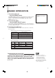
BASIC OPERATION 1. To turn the power on: Push the POWER switch. The POWER indicator glows green. The mode and color system of an input signal are automatically discerned and displayed on screen for about 3 seconds. To turn off power, push the POWER switch again, and the POWER indicator goes off. VIDEO A + Input mode NTSC + Color system 2. To select the input: Push an INPUT SELECT switch. Push VIDEO A, VIDEO B, RGB/COMPO(SDI) or Y/C.
PICTURE ADJUSTMENTS Turn a separate front panel control to adjust picture contrast, picture brightness, picture color density, and picture hue respectively: CONTRAST (picture contrast) CONTRAST Softer Clearer BRIGHT (picture brightness) BRIGHT Darker NOTE Brighter ● To adjust the CHROMA and PHASE controls more precisely, input the color bar signal and operate the BLUE CHECK function as follows: CHROMA (picture color density) After inputting the color bar signal, push the front panel BLUE CHECK swi
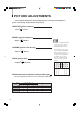
VIDEO SIGNAL CONTROLS Push each switch to ON or OFF for video signal control. UNDER SCAN Push the UNDER SCAN switch to reduce the dimensions of display area so the whole picture is displayed on screen. Use to check the picture frame. PULSE CROSS Push the PULSE CROSS switch to simultaneously display two blank areas crossed horizontally and vertically on screen (“Pulse Cross” display) by delaying the phase of the input signal.
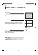
ON-SCREEN MENU CONTROLS By calling up the menu display on screen, various functions can be selected and set as needed. NOTE Calling up the menu display, selecting an item 1. Press the MENU button to call up the menu display on screen (see 1 ● When the menu display 1 (shown at left below) is on screen, press the ENTER button. The display changes to 2 (shown below center). In this state, you can also select the item or change the setting. ● When the display 2 is on screen, below).
ON-SCREEN MENU CONTROLS (continued) PEAKING FREQ./PEAKING LEVEL (picture quality improvement) Corrects the luminance signal to improve picture quality by changing peak frequency and/or peak level depending on the video signal input to the monitor. Use PEAKING FREQ. to set correction frequency. Use PEAKING LEVEL to set correction level. Setting (ferquency) ● When analog RGB signals are input to the monitor, the indications do not appear and the functions cannot be operated. Function 2.
MEMORY MODE A set of picture settings can be programmed in memory for quick recall when necessary. Recall/release of memory mode Press the MEMORY MODE switch to recall a set of picture settings programmed in memory. Pressing the switch locks the functions of the front-panel PHASE, CHROMA, BRIGHT, CONTRAST controls, and remote-control picture adjustments not to be operated. Press again to release memory mode.
MEMORY MODE (continued) 3. Press the ▲ or ▼ button to select a function to be revised. Press the ENTER button after selecting PICTURE ADJUSTMENT to call up display 2. qMEMORY MODE REV I SE CONTRAST :0 BR I GHT :0 CHROMA :0 PHASE :0 ENTER : After making all settings on screen, press the MENU button to make display 1 appear. 4. Press the or button to change the set level. 2 Adjustable CONTRAST, BRIGHT, CHROMA or PHASE range depends on each set level previously stored in memory.
SET-UP FOR MONITOR INSTALLATION When installing the monitor, make set-up adjustments required for the picture settings to match conditions where the monitor is to be used. To call up SET-UP MENU and select a function: 1. To make 1 (SET-UP MENU) appear, with the ENTER button pressed, press the MENU button. 2. Press the ▲ or ▼ button to select an adjustment item.
SET-UP FOR MONITOR INSTALLATION (continued) WHITE BALANCE ADJUST (white balance adjustments) Before making these adjustments, select the color temperature 9300K or 6500K on MENU. Adjustment (level) NOTE ● By making white balance adjustments on SET-UP MENU, ✻ appears to the right of the COLOR TEMP. setting on MENU Function RED DRIVE (-10,-9…0…+9, +10) Adjusts the drive level of a red signal component. GREEN DRIVE (-10,-9…0…+9, +10) Adjusts the drive level of a green signal component.
SET-UP FOR MONITOR INSTALLATION (continued) STATUS DISPLAY (setting the status display to on/off) When the power is turned on or the input mode is switched, the status display (color system and input mode) appears on screen. The display can be set to on or off. Setting Function ON Status display appears. OFF Status display does not appear.
PICTURE SETTING INITIALIZATION The MENU and/or SET-UP MENU settings, including changes added later by the user, can be reset (initialized) to their initial (default) settings. To initialize MENU settings only MENU settings (except MEMORY MODE and RGB/COMPO(SDI)) can be exclusively reset: NOTE ● For initial (default) MENU settings, see page 21. 1. With the ▼ button pressed, press the MENU button to display 1 on screen. 2. ● Press the ENTER button to reset.
REMOTE CONTROLS The optional wireless remote control unit (RM-C550W) operates the following: ● On-screen menu functions (MENU, SET-UP MENU, etc.) ● Picture adjustments (CONTRAST, BRIGHT, CHROMA, PHASE) ● Sound adjustments (VOLUME, MUTE) On-screen menu remote operation Remote keys and front controls with the same designation share the common functions. For detailed operation, see instructions about each menu function in this manual.
EACH REMOTE CONTROL OF PLURAL MONITORS To operate or adjust plural units of monitors, by programming and assigning an ID number (00 to 99) for each monitor, a specified monitor can be remote-controlled. To program an ID number (use front controls): 1. Press the POWER switch to turn the power off. 2. With the ▼ and MENU buttons pressed, press the POWER switch to turn q I N I T I ALIZE MENU r I D NUMBER SE T qSE T - UP MENU rRE SE T ENTER the power on. Keep pressing the ▼ and MENU buttons until 1 appears.
BEFORE CALLING FOR SERVICE Before concluding a problem has occurred, check the following points. If the problem persists after carrying out the checks, disconnect the power cord from the AC outlet and consult the dealer from whom you purchased the monitor. Problems Measures Is MEMORY MODE switched on? Switch off. Is CONTROL LOCK activated? Deactivate it. Abnormal picture adjustments with all controls at centre. Are PICTURE ADJUST menu settings changed via remote control? Reset to standard settings.
MENU DISPLAY CHART The initial (default) adjustments/settings are shown in the menus below. When the monitor was shipped from the factory, the NTSC SETUP had been set to 7.5 and the COMPO. LEVEL to BETA 75. For PICTURE ADJUST MENU via remote control, see page 18. MENU Menu functions qMENU r ASPECT RAT I O :4-3 F I L TER SE LEC T :COMB PEAK I NG FREQ. :2.6MHZ PEAK I NG LEVEL:0dB AFC :NORMAL COLOR TEMP. :6500 SETUP NTSC :7.5 COMPO.
SPECIFICATIONS Type Color systems Picture tube : Color video monitor : NTSC 3.58 MHz, NTSC 4.43 MHz, PAL : [BM-H1900SU] 19" (47.5 cm) diagonally measured, 90° deflection, in-line gun, mediumhigh-definition cathode-ray tube, triodot type (dot pitch of 0.4 mm), SMPTE-C phosphor [BM-H1310SU] 13" (33 cm) diagonally measured, 90° deflection, in-line gun, high-definition tinted cathode ray tube, trio-dot type (dot pitch of 0.
DIMENSIONS BM-H1310SU ❋ The faceplate dimensions shown are larger than the visible portion of screen (Screen size). 13-5/8" (346mm) MENU DEGAUSS CHROMA BRIGHT CONTRAST POWER VIDEO A RGB/ B COMPO(SDI) Y/C EXT SYNC ON OFF ENTER INPUT SELECT 3-3/8" (83.5mm) Front 13"(327.
BM-H1900SU / BM-H1310SU COLOR VIDEO MONITOR JVC PROFESSIONAL PRODUCTS COMPANY DIVISION OF US JVC CORP. 1700 Vallery Road Wayne, NJ07470 JVC CANADA INC.