NETWORK CODEC DM–NC40 CF For Customer Use : Enter below the Serial No. which is located on the body. Retain this information for future reference. Model No. DM-NC40 Serial No. INSTRUCTIONS ENCODE DECODE HOLD IN 1 PLAY STOP HOLD SELECT IN 2 POWER P inP This instruction book is mode from 100% recycled paper.
IMPORTANT SAFEGUARDS 1. 2. 3. 4. 5. 6. 7. 8. 9. 10. 11. 12. 13. 14. 15. 16. 17. 18. 19. 2 Read all of these instructions. Save these instructions for later use. All warnings on the product and in the operating instructions should be adhered to. Unplug this appliance system from the wall outlet before cleaning. Do not use liquid cleaners or aerosol cleaners. Use a damp cloth for cleaning. Do not use attachments not recommended by the appliance manufacturer as they may cause hazards.
SAFETY PRECAUTIONS FOR USA AND CANADA CAUTION RISK OF ELECTRIC SHOCK DO NOT OPEN AUTION : TO REDUCE THE RISK OF ELECTRIC SHOCK, DO NOT REMOVE COVER (OR BACK). NO USER SERVICEABLE PARTS INSIDE. REFER SERVICING TO QUALIFIED SERVICE PERSONNEL. WARNING: TO REDUCE THE RISK OF FIRE OR ELECTRIC SHOCK, DO NOT EXPOSE THIS APPLIANCE TO RAIN OR MOISTURE. This unit should be used with 120V AC only. CAUTION: To prevent electric shocks and fire hazards, do NOT use any other power source.
Features Thank you for purchasing this JVC product. Before operating this unit, please read this instructions carefully to ensure the best possible performance. These instructions are for DM-NC40U. Video/Audio codec ISMA streaming The unit is equipped with both encoding and decoding features. The unit is also equipped with an echo canceller feature. ISMA-compliant video and audio streaming. Contact the nearest JVC-authorized service agent for details concerning ISMA-compliant players.
Introduction Introduction Contents Step 5 Mode Setup 5-1 Setting in the MODE SETUP Screen ........... 29 Features ................................................................ 4 Contents ................................................................ 5 Step 6 Detailed Setup Operational Environment ...................................... 6 6-1 NETWORK SETUP screen ................... 30 Cautionary Notes .................................................. 7 6-2 ENCODE PARAMETERS screen .........
Operational Environment The operational environment is as of September 2003. For the latest operational environment, please consult the person in charge of professional equipment at your nearest JVC-authorized service agent. Compatible PC The following operation environment is required when connecting a PC to this unit.
Storage/usage location ■ Do not use or store the unit in the following locations. Malfunction may occur as a result. • Location outside the allowed operating temperature range (0°C ~ 40°C) where the temperature may become extremely hot or cold. • Location outside the allowed operating humidity range (30% ~ 80%) where the humidity is high. • Location with strong magnetic force such as from a transformer, motor, etc. • Location with presence of electric waves such as from a transceiver, mobile phone, etc.
Names and Operations of Parts Front !1 CF ENCODE DECODE HOLD IN 1 PLAY STOP HOLD SELECT IN 2 POWER P inP q !0 o i u y 1 [POWER] Power button and display lamp Turns the unit power on and off. Press securely until a click is heard. The display lamp turns green when the power is on.
Introduction Back SERIAL 1 ALARM RS485 IN AUDIO OUT SERIAL 2 SERVICE RS232C VIDEO IN 1 VIDEO OUT CONTROL VIDEO IN 2 AC IN L LOOP THRU LOOP THRU 100BASE-TX R OPEN RESERVED @2 @1 @0 !9 0 Connection number display While in the Teleconference or Monitor mode, the connecting destination number is displayed. The display will flash when establishing connection and the lamp will change to a constant display when connection is established.
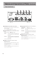
Names and Operations of Parts (Continued) Back (Continued) @3 @4 @5 ALARM @7 SERIAL 1 RS485 AUDIO OUT IN @6 VIDEO OUT SERIAL 2 SERVICE RS232C VIDEO IN 1 CONTROL VIDEO IN 2 AC IN L LOOP THRU LOOP THRU 100BASE-TX R RESERVED M [ALARM] Alarm port (Dsub 15-pin, female) Input terminals for alarm signals, and output terminals for device control.
Various Applications Teleconferencing (Connection example: page 13) CH-1 CH-2 PROFESSINAL AUDIO LEVEL CF ENCODE DECODE HOLD IN 1 PLAY STOP HOLD SELECT IN 2 POWER P inP FOCUS IRIS OPEN ND FILTER ON OFF Preparations Live video/audio can be sent/received.
Preparation Flow Perform settings using the steps shown below. Step 1 Connection/Installation • Connect cables to the back of the unit. Page 13 ~ • For recording, insert a CF card • When completed, turn on the power. Step 2 PC Network Settings • Network settings for the unit have been performed at the time of shipment. Page 20 ~ First, perform network settings for the connecting PC.
Step 1 Connection/Installation Preparations 1-1 Connection Examples (1) Teleconference system CH-1 CH-2 PROFESSINAL VIDEO OUT AUDIO LEVEL ON OFF IRIS FOCUS OPEN ND FILTER AUTO MANU DV CAMCORDER GY-DV300 PUSH AUTO AUDIO OUT AUDIO IN VIDEO IN 1 SERIAL 1 ALARM RS485 IN AUDIO OUT VIDEO OUT VIDEO IN 1 Teleconference mode ( page 29) SERIAL 2 SERVICE RS232C CONTROL VIDEO IN 2 AC IN L LOOP THRU LOOP THRU 100BASE-TX 100BASE-TX R RESERVED V. IN A.
Step 1 Connection/Installation (Continued) 1-1 Connection Examples (Continued) (2) Remote monitoring system Bidirectional audio conference is available. The units can reconnect automatically by power on after power failures. (CF card recording can only be performed on the camera side. Recording on the monitoring side is not available.
When using the unit in the ISMA Server mode, an ISMA-compliant player is required. For details of ISMA compliant player, please consult the person in charge of professional equipment at your nearest JVC authorized service agent.
Step 1 Connection/Installation (Continued) 1-1 Connection Examples (Continued) Caution when connecting different modes For teleconference application, set units to Teleconference mode. For remote monitoring application, set units to Camera/Monitor mode. Connecting units in different application modes will result some problems as following: Teleconference mode - Monitor mode Teleconference side: Audio of the monitor side is played back. Video will not be played back.
Preparations 1-2 Connecting a LAN Cable Connect the unit to a hub or a PC using a LAN cable. For the cable, select category 5 or higher. ALARM SERIAL 1 RS485 DIO OUT VIDEO OUT SERVICE RS232C VIDEO IN 1 OPEN When connecting to a hub: Use a straight cable. CONTROL VIDEO IN 2 LOOP THRU RESERVED SERIAL 2 LOOP THRU 100BASE-TX When connecting to a PC: Use a cross cable.
Step 1 Connection/Installation (Continued) 1-4 SERIAL Ports and ALARM Port Signal names of SERIAL ports and ALARM port located on the back of the unit are shown below. [SERIAL 1, 2] Serial ports 1, 2 (Dsub 9-pin, male) [ALARM] input port for alarm and output port for control (Dsub 15-pin, female) When viewing from the back of unit SERIAL 1 port (when set to RS485) SERIAL 1 port (when set to RS232C) SERIAL 2 port Pin no. 1 2 3 4 5 6 7 8 9 Signal name NC RXD TXD NC GND NC NC NC NC Pin no.
Connect the unit to AC120V outlet using the included power cord. Fix the cord using the locking bracket. • • Do not use the included cord other than for this unit. To completely cut-off power, remove the power plug from the wall outlet or remove the power cord from the AC IN terminal of the unit. Use of a cord other than that specified or a cord that has been damaged may result in fire or electrical shock.
Step 2 PC Network Setup 2-1 Setting the IP Address of the PC (For Windows XP) When connection and installation are completed, the IP address of the PC controlling the unit is set. For Windows XP, perform the setting using the steps shown below. (For Windows 2000, see page 22) 1. Click • Right click “My Network” and select 2. . Select the network of the PC that will be used for Web browser operations • Right click and select . Confirm that the checkbox is selected.
Preparations 4. Set the IP address 1 Select “Use the following IP address”. 2 Set “IP address”. (For use at default setting without DHCP server, enter 10.0.0.100) Memo • Always take a memo of the original IP address before making changes. • Do not use the same IP addresses within a LAN. 3 Enter appropriate values for “Subnet mask”. If unknown, ask to your network administrator. (For compatibility with default settings use 255.0.0.0) 4 If there is a “Default gateway”, enter the IP address.
Step 2 PC Network Settings (Continued) 2-2 Setting the IP Address of the PC (For Windows 2000) When connection and installation are completed, the IP address of the PC controlling the unit is set. For Windows 2000, perform the setting using the steps shown below. (For Windows XP, see page 20). 1. Click . • Click “Settings” → “Network and dialup connections”. 2. Select “Local Area Connections” • Right click and select . 1 Click . 3. Select “Internet Protocol (TCP/IP)” and click .
Preparations 4. Set the IP address 1 Select “Use the following IP address”. 2 Set “IP address”. (For use at default setting without DHCP server, enter 10.0.0.100) 3 Enter appropriate values for “Subnet mask”. If unknown, ask to your network administrator. 4 If there is a “Default gateway”, enter the IP address. (For example, 10.0.0.254) 5 Click 5. Click . in the “Local Area Connection Properties” dialog box 1 Click .
Step 3 Launching the Web Browser Settings for the unit are performed using a Web browser. Login as an administrator to perform settings. 3-1 About the Web Browser About Web page images Look and feel of Web pages may slightly differ from the printed images in this Manual depending on Web browser or PC display settings. If not all items within the page are displayed, resize the browser window, etc. to display all items. Printed pages in this manual are screen copy of Internet Explorer as examples.
Preparations 3-2 About Access Restriction levels DM-NC40 has 3 access levels for protection of settings/data.
Step 3 Launching the Web Browser (Continued) 3-3 Launching the Browser When the IP address of DM-NC40 is specified in the Web browser and login as an administrator is performed, the initial setup (STATUS) screen is displayed. 1. Launch the Web browser 1 Enter the IP address of the unit. (Factory setting, 10.0.0.1, is available when there is no DHCP server.) 2 Click “Go”. Memo Direct specification of the IP address may not be possible when a proxy server is used for Internet access.
Step 4 Initial Settings DHCP of the unit is enabled in factory settings. When DHCP server is available in the network, see page 30. DHCP of the unit can be disabled using API. In this case you can change the IP address of the unit as following. 1. Click “Detailed Setup” on the left of the Network Codec screen and then click “Network Setup” • The NETWORK SETUP screen is displayed. 1 Change the IP address to the address assigned by network administrator or per mitted address. 2 Set the subnet mask.
Step 4 Initial Settings (Continued) 4-2 Time Setup (Be sure to perform) Set the time and date of the unit. Be sure to perform these settings since they are used as file names of JPEG recorded to the CF card. 1. Click “Time Setup” on the left of the Network Codec screen • The TIME SETUP screen will be displayed. 1 Select the country/region of use. Memo The “Second” is for display only and cannot be entered or changed. 2 Enter the year, month, date, hour and minute.
Step 5 Mode Setup Preparations 5-1 Setting in the MODE SETUP screen (Be sure to perform) Select mode of the unit according to the system of use. 1. Click Mode Setup in the Network Codec screen • The MODE SETUP screen is displayed. 1 Select the mode. (Factor y setting: CAMERA mode) 2 Click “Initialize to Preset Values” to reset to the initial values of the mode selected in 1. Memo When clicking this button, the HOLD display lamp will turn on and panel operations will be locked.
Step 6 Detailed Setup 6-1 NETWORK SETUP screen Network related settings can be made on NETWORK SETUP screen. Click Network Setup on the left of the Network Codec screen to display the NETWORK SETUP screen. Select the screen Enter Enter Multicast is stopped when current mode is changed to another. Click For details of network settings, ask to network administrator.
Preparations Optional settings (set as needed) Item Host Name Domain Name DNS Server NTP Server NTP Refresh Interval IP Broadcast RTSP Server Acceptance Multicast Multicast Address Memo Content A name for distinguishing the unit connected to a network is set. Allowed characters are alphanumerical characters, hyphen (-) and period (.). Maximum number of characters allowed is 64. Names can be set individually for a system connected with multiple DM-NC40 units.
Step 6 Detailed Setup (Continued) 6-2 ENCODE PARAMETERS screen Encoding related settings can be performed on the ENCODE PARAMETERS screen. Click Encode Parameters on the left of the Network Codec screen to display the ENCODE PARAMETERS screen. Current setting of bitrate is displayed. 1 The bitrate is selected by directly clicking the select bar. 2 Fine adjustments are made using the and buttons. Select the screen Bitrate being changed by adjust buttons or clicking is displayed.
• When the Video Frame Rate is set to High (H), Mid (M) or Low (L), the value of frame rate will be as follows, depending on the selected bitrate.
Step 6 Detailed Setup (Continued) 6-3 TELEPHONE BOOK screen Registration of destination address can be performed on the TELEPHONE BOOK screen. Click Telephone Book on the left the Network Codec screen to display the TELEPHONE BOOK screen. Registered IP addresses are listed. Select the screen Enter Click “Add to Book” to register entered values. To delete the registered number, enter “Edit No.” and click “Del from Book”. Item Edit No.
Security related setting can be performed on the SECURITY SETUP screen. Click Security Setup on the left of the Network Codec screen to display the SECURITY SETUP screen. Select the screen Click “Change” to display the Change Setting screen. Change Setting Screen Enter the current user name. Enter the current password. Enter the new user name. Enter the new password. Enter the new password again.
Step 6 Detailed Setup (Continued) 6-4 SECURITY SETUP screen (Continued) Item Content Password For telnet The password required for Telnet via network, or Terminal nc40api software via serial port can be changed. (Fixed) dm-nc40 Web Browser: Administrator Account information (user name and password) of Administrator for access using the Web browser can be changed. admin dm-nc40 Web Browser: Operator Password of Operator for access using the Web browser can be changed.
Alarm input related settings can be performed on the ALARM SETUP screen. Click Alarm Setup on the left the Network Codec screen to display the ALARM SETUP screen. Select from the pull-down menu Select one Select from the pull-down menu. Select the screen Enter Enter destination IP address and parameters for forwarding alarm Select from the pull-down menu Click settings.
Step 6 Detailed Setup (Continued) 6-5 ALARM SETUP screen (Continued) Item Input Pin * Following settings are to be performed for each pin. Content Select the pin no. of the alarm port to set. [Variable: 1~4] Default value 1 Trigger Select the polarity of the alarm input signal. Input signal is invalid when setting to Disable. [Variable: Low, High, Disabled] Disabled Trigger Duration Set the length of input signal to assume as an alarm.
The polarity of output pins can be set on the OUTPUT PIN SETUP screen. Click Output Pin Setup on the left of the Network Codec screen to display the OUTPUT PIN SETUP screen. Select one for each item Select the screen Click settings. Item Output Pin 1 ~ 8 Content Set high or low to output pins in the alarm port. High: Outputs high level Low: Outputs low level (Outputs are TTL level.) to confirm Default value High * These output pins are not alarm output of the unit.
Step 6 Detailed Setup (Continued) 6-7 SERIAL PORT SETUP screen Serial I/O port related settings can be performed on the SERIAL PORT SETUP screen. Click Serial Port Setup on the left of the Network Code screen to display the SERIAL PORT SETUP screen. Select from the pull-down menu Select one for each item Enter Select from the pull-down menu Select one Select the screen Default values are same for both Serial 1 and Serial 2 ports.
CF card recording related settings can be performed on the CF CARD SETUP screen. Clicking CF Card Setup on the left of the Network Codec screen to display the CF CARD SETUP screen. (For details concerning CF cards, see “Compatible CF Cards”, page 6) Select one [Format] Displayed Select one [Del Files] Memo Select the screen Operations will not be accepted while formatting or deleting files. Select one for each item Item No.
Operating the Teleconference System In the Teleconference mode, both videos of teleconference can be displayed on a single 2 by PinP. monitor Connected party CF Number display ENCODE DECODE HOLD IN 1 PLAY STOP HOLD SELECT 4.7. IN 2 User POWER P inP Network 6. 1. Teleconference mode 1. Set the power to ON. (Off) The number display circles, IP address is displayed as shown on page 48, and then turns off when ready. CF Number display 2.
When connection is established: 5. The display will change to a constant display and the video of the connect party will be displayed. The display will change to a constant display and the video of the connect party will be displayed. 6. Press the PinP button 6. The videos of the user and the connected party will be displayed. 7. Press the STOP button Connection will be disconnected and the number display and video display will be cleared.
Operating the Monitor System For use as a Monitor system, the DM-NC40 connected to the camera side is set to the Camera side Camera mode and the DM-NC40 on the monitoring side is set to the Monitor mode. Camera side CF ENCODE DECODE HOLD IN 1 PLAY STOP HOLD SELECT IN 2 Monitoring side POWER Network P inP 1. Number display CF Number display 2. ENCODE DECODE HOLD IN 1 PLAY STOP HOLD SELECT 3. IN 2 POWER P inP 1. Camera mode Monitor mode 1. 1.
Press the VIDEO SELECT button 6. VIDEO IN 1 and VIDEO 2 videos will switch every time the button is pressed. 7. Press the STOP button Press the VIDEO SELECT button VIDEO IN 1 and VIDEO 2 videos will switch every time the button is pressed. 7. Operations 6. Press the STOP button Connection will be disconnected and the number displayed will be cleared. Connection will be disconnected and the number displayed will be cleared. ■ Multicast send/receive signals ( See page 34) 1.
Operating the Monitoring System (Continued) H Av Pk L H ALC LEVEL Av Pk L ALC LEVEL Web browser can get and display JPEG images from camera mode. ALARM SERIAL 1 RS485 IN AUDIO OUT VIDEO OUT SERIAL 2 SERVICE RS232C VIDEO IN 1 CONTROL VIDEO IN 2 AC IN L LOOP THRU LOOP THRU 100BASE-TX R RESERVED OPEN OPEN Amplifire Network Refreshing images • Up to 3 JPEG images from the unit can be displayed per second. • To refresh an image, press the Refresh button on the browser.
Operating the ISMA Server System To play the stream from ISMA Server mode, ISMA-complaint player is required. 2 are 2 types of streaming: unicast that-is available only for one client, and multicast that There is available for multiple clients. Operation of player differs depending on the streaming type. 1Å@ÉpÉ\ÉRÉìÇÃIPÉAÉhÉå Server side ENCODE DECODE HOLD IN 1 PLAY STOP HOLD SELECT IN 2 Operations CF Player side POWER P inP Network Number display Perform the following steps on PC.
DHCP Operation and IP Address Display during Startup DHCP Operation DM-NC40 supports DHCP. If there is DHCP server in same LAN, network settings, i.e. IP address, subnet mask, default gateway, are provided from the DHCP server to the unit after power on or rebooting. After turning on the power or rebooting, the unit displays IP address. If there is DSCP server in same LAN, provided IP address from the DHCP server will be displayed on the front of the unit.
Operating the CF card JPEG files can be recorded to the CF card. Formatting CF card and deleting JPEG files are available from Web browser. Seeing JPEG files is available from PC. Format – – See – Delete Operations CF CARD SETUP screen Card reader Via FTP : Allowed, – : Not allowed Operating in the CF CARD SETUP screen In the CF CARD SETUP screen, the CF card can be formatted and image files can be deleted. Login as an administrator to perform settings.
Operating the CF card (Continued) Operating with CF Card Reader With the CF card reader, you can read image files recorded in a CF card. Remove the CF card from DM-NC40 and set it to the CF card reader. Caution: Windows cannot read CF cards formatted to Ext2. Please format the CF card to FAT32. Image files are recorded in CF cards as follows. You can open the files using standard software on Windows. You can also move, copy, or delete files with standard Windows software.
Operating of FTP 1. From the command prompt of PC, type “ftp” to login. Default settings of DM-NC40, 10.0.0.1 as IP address, OPERATOR as user, and dm-nc40 as password, are used in following steps. 1 Enter “10.0.0.1” (IP address of the unit) after “ftp” and press the Enter key. 2 Enter “OPERATOR” for User and press the Enter key. 3 Enter “dm-nc40” for Password and press the Enter key. (Password will not be displayed) 2. Type “ls” to list image files or directories 4 Enter “ls” and press the Enter key.
Operating the CF Card (Continued) 3. Use “cd” command to change directory, and type “ls” to list files in the directory. 1 Type “cd” + path of directory to move to the directory. (Here, jpeg-1 directory of alarm1 is selected.) 2 Enter “ls” and press the Enter key. 3 File names in current directory are displayed. 4. Use “get” command to copy files from CF card to PC. 1 Enter “get” + file name of image and press the Enter key. 2 Transfer file to the C drive as pict1.
Settings Using the Terminal Software of a PC Connection During the power of the unit is off, connect the SERIAL 2 port of the unit to the COM port of the PC with cross cable. Set the Protocol select switch of Serial Port 2 to SERVICE. Memo Operations Some PC may restart the unit when PC is turned on with the unit connected to PC via serial port. Start terminal software on the PC. Launch the terminal software using the PC.
Settings Using the Terminal Software of a PC (Continued) Command Table (none of the commands require arguments) Command name stat set mode set mode Camera set mode Monitor set mode Teleconference set mode ISMA_Server set mode User_Mode_xxx set aec set aec on set aec off set tcp set tcp on set tcp off .set brmon start .
Connection Connect the unit and PC using a network. Ping command is available to test connection via network. Example: If the IP address of the unit is 10.0.0.1 (factory set IP address) 1. Start command prompt on the PC. 2. Type “ping 10.0.0.1”. 3. If setting and connection are correct, responses such as shown below will be displayed. “Reply from 10.0.0.1: bytes: 32 time tieme<10ms TTL=64” If there is some problem, the following timeout error will be displayed. “Request timed out.
About the Alarm In camera mode, image files are recorded to CF card when the CF button is pressed or alarm is inputted to the ALARM INPUT port. (To see the image, see “Operating the CF Card”, page 49) Settings ● Select input video Select input video for JPEG in the ENCODE PARAMETERS screen. “Video In 1” or “Video In 2”. ● Alarm input settings Polarities of ALARM INPUT 1 -4 (pin 9 - 12th in Dsub for alarm), recording time, etc. are set in the ALARM SETUP screen.
About the Alarm (Continued) When alarm settings are set to send alarm information to DM-NC40 with API, the monitor mode DM-NC40 that receives the notification works as follows: (For details on settings, see page 37) 1. If the source unit is registered in the telephone book, the number of source unit flashes on the number display of the monitor unit. 2. If the monitor is connected to another unit, the connection is disconnected when the PLAY button is pressed, and new connection to the source unit is made.
Specifications Compressions format External dimensions (unit: mm) 301 MPEG-4 JPEG Frame sizes: MPEG-4 352 240, 176 120 JPEG 704 480 or MPEG-4 320 240, 160 120 JPEG 640 480 Frame rates MPEG4: 30fps max JPEG 3fps max Encode rate: 2.0Mbps max (ISMA compliant)
DM-NC40 NETWORK CODEC VICTOR COMPANY OF JAPAN, LIMITED ® ® is a registered trademark owned by VICTOR COMPANY OF JAPAN, LTD. is a registered trademark in Japan, the U.S.A., the U.K. and many other countries.