
Operation Manual


EN 7
GETTING STARTED
MasterPage: Start_Right
GETTING STARTED
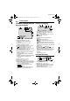
Controls
a Menu Button [MENU] (墌 pg. 36)
Data Battery Button [BATT. DATA] (墌 pg. 14)
B E-Mail Clip Recording Button [E-MAIL]
(墌 pg. 31)
Index Button [INDEX] (墌 pg. 30)
C D.S.C. Playback Select Button [SEL]
(墌 pg. 29)
Thumbnail Storing Button [STORE]
(墌 pg. 48)
D Information Button [INFO] (墌 pg. 30)
E Set Button [SET] (墌 pg. 36)
F Fast-Forward Button [
5
] (墌 pg. 22)
LED Light Button [LIGHT] (墌 pg. 42)
Right Button [>] (墌 pg. 36)
G Stop Button [8] (墌 pg. 22)
Backlight Compensation Button [BACK
LIGHT] (墌 pg. 45)
Down Button [ ] (墌 pg. 36)
H Rewind Button [
3
] (墌 pg. 22)
Quick Review Button [Q.REVIEW] (墌 pg. 21)
Left Button [<] (墌 pg. 36)
I VIDEO/MEMORY Switch (墌 pg. 15)
J Play/Pause Button [4/9] (墌 pg. 22)
Manual Focus Button [FOCUS] (墌 pg. 44)
Up Button [ ] (墌 pg. 36)
K Diopter Adjustment Control (墌 pg. 16)
L Battery Release Button [BATT. RELEASE]
(墌 pg. 14)
M Snapshot Button [SNAPSHOT]
(墌 pg. 27, 43)
Live Slow Button [SLOW] (墌 pg. 36, 42)
N Power Zoom Lever [T/W] (墌 pg. 20)
Speaker Volume Control [VOL. +, –]
(墌 pg. 22)
O Cassette Open/Eject Switch [OPEN/EJECT]
(墌 pg. 17)
P Recording Start/Stop Button (墌 pg. 19)
Q Power Switch [A, M, PLAY, OFF] (墌 pg. 15)
R Lock Button (墌 pg. 15)
Connectors
The connectors are located beneath the covers.
S S-Video Input/Output Connector [S]
(墌 pg. 23, 51)
T Microphone connector [MIC] (墌 pg. 54)
U USB (Universal Serial Bus) Connector
(墌 pg. 53)
V Digital Video (i.Link*) Connector [DV IN/OUT]
(墌 pg. 52, 53)
* i.Link refers to the IEEE1394-1995 industry
specification and extensions thereof. The logo
is used for products compliant with the i.Link
standard.
W Audio/Video Input/Output Connector [AV]
(墌 pg. 23, 51)
X DC Input Connector [DC] (墌 pg. 13)
Indicators
Y POWER/CHARGE Lamp (墌 pg. 13, 19)
Other Parts
Z LCD Monitor (墌 pg. 19, 20)
a Shoe
(Before you purchase optional shoe
accessories, make sure the items are
compatible and can attach to the shoe on
your camcorder. There may be cases where a
part of an accessory item obtrudes onto the
camcorder’s body, preventing attachment to
your unit.)
b Viewfinder (墌 pg. 16)
c Speaker (墌 pg. 22)
d Battery Pack Mount (墌 pg. 14)
e Cassette Holder Cover (墌 pg. 17)
f Lens
g LED Light (墌 pg. 42)
(When using an optional conversion lens, it
may cover this area and block the light.)
h Remote Sensor (墌 pg. 24)
i Camera Sensor
(Be careful not to cover this area, a sensor
necessary for shooting is built-in here.)
j Stereo Microphone (墌 pg. 54)
k Shoulder Strap Eyelet (墌 pg. 12)
l Grip Strap (墌 pg. 16)
m Card Cover [MEMORY CARD] (墌 pg. 18)
n Tripod Mounting Socket (墌 pg. 17)
o Stud Hole (墌 pg. 17)
GR-DF550US.book Page 7 Thursday, February 24, 2005 11:17 AM