ENGLISH CONTENTS SAFETY PRECAUTIONS PROVIDED ACCESSORIES GETTING STARTED DIGITAL VIDEO CAMERA GR-DVF21 GR-DVF11 Please visit our CyberCam Homepage on the World Wide Web and answer our Consumer Survey (in English only): http://www.jvc-victor.co.jp/english/index-e.html 2–5 5 6 – 11 Power ............................................ 6 Date/Time Settings ............................ 8 Loading/Unloading A Cassette ............... 9 Recording Mode Setting ..................... 10 Grip Adjustment ............
EN Dear Customer, Thank you for purchasing this digital video camera. Before use, please read the safety information and precautions contained in the following pages to ensure safe use of this product. Using This Instruction Manual •All major sections and subsections are listed in the Table Of Contents on the cover. •Notes appear after most subsections. Be sure to read these as well. •Basic and advanced features/operation are separated for easier reference. It is recommended that you . . . ....
EN IMPORTANT PRODUCT SAFETY INSTRUCTIONS Electrical energy can perform many useful functions. But improper use can result in potential electrical shock or fire hazards. This product has been engineered and manufactured to assure your personal safety. In order not to defeat the built-in safeguards, observe the following basic rules for its installation, use and servicing. ATTENTION: Follow and obey all warnings and instructions marked on your product and its operating instructions.
EN USE SERVICING 1. Accessories 1. Servicing To avoid personal injury: •Do not place this product on an unstable cart, stand, tripod, bracket or table. It may fall, causing serious injury to a child or adult, and serious damage to the product. •Use only with a cart, stand, tripod, bracket, or table recommended by the manufacturer or sold with the product. •Use a mounting accessory recommended by the manufacturer and follow the manufacturer’s instructions for any mounting of the product.
EN SAFETY PRECAUTIONS Do not point the lens or the viewfinder directly into the sun. This can cause eye injuries, as well as lead to the malfunctioning of internal circuitry. There is also a risk of fire or electric shock. PROVIDED ACCESSORIES CAUTION! The following notes concern possible physical damage to the camcorder and to the user. When carrying, be sure to always securely attach and use the provided shoulder strap.
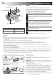
GETTING STARTED EN Battery pack BN-V207U or BN-V214U Power This camcorder’s 2-way power supply system lets you choose the most appropriate source of power. Do not use provided power supply units with other equipment. CHARGE indicator POWER indicator CHARGING THE BATTERY PACK To AC outlet AC Power Adapter/Charger AA-V20U 1 Make sure you unplug the camcorder’s DC cord from the AC Power Adapter/Charger. Plug the AC Adapter/ Charger’s power cord into an AC outlet. The POWER indicator lights.
EN 7 USING THE BATTERY PACK BATTERY RELEASE Switch 1 Hook the non-terminal end of the battery pack to the camcorder and push the battery pack in until it locks in place . •If the battery pack is attached in the wrong position, a malfunction may occur. Approximate recording time B Push in. A Hook on. ATTENTION: Before detaching the power source, make sure that the camcorder’s power is turned off. Failure to do so can result in a camcorder malfunction.
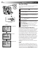
GETTING STARTED (cont.) EN Date/Time Settings The date/time is recorded onto the tape at all times, but its display can be turned on or off during playback (Z pg. 31). MENU/BRIGHT Dial M A Set the Power Switch to “ ”. The power lamp lights and the camcorder is turned on. 4 Move the highlight bar to “TO DATE/TIME MENU” by rotating MENU/BRIGHT. Press it and the Date/ Time Menu appears. 5 Move the highlight bar to “DATE/TIME” by rotating MENU/BRIGHT.
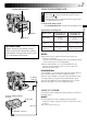
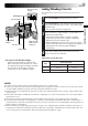
EN OPEN/EJECT Switch Cassette holder PUSH OPEN Button Cassette cover Loading/Unloading A Cassette The camcorder needs to be powered up to load or eject a cassette. 1 2 Press PUSH OPEN and open the LCD monitor. 3 Insert or remove a tape and press “PUSH HERE” to close the cassette holder. •Once the cassette holder is closed, it recedes automatically. Wait until it recedes completely before closing the cassette cover. •When the battery’s charge is low, you may not be able to close the cover.
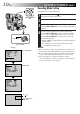
GETTING STARTED (cont.) EN Recording Mode Setting Set depending on your preference. MENU/BRIGHT Dial M A F OF Power lamp PLAY Power Switch Display FOCUS EXPOSURE W. BALANCE FADER / WIPE P.
EN Grip Adjustment 1 2 3 Recording Start/Stop Button Separate the Velcro strip. Pass your right hand through the loop and grasp the grip. Adjust so that your thumb and fingers can easily operate the Recording Start/Stop Button and the Power Zoom Lever. Refasten the Velcro strip. Viewfinder Adjustment Diopter Adjustment Control 1 Set the Power Switch to “ ” or “ ”. The power lamp comes on and the camcorder is turned on.
RECORDING Basic Recording EN Shooting While Watching The Viewfinder NOTE: You should already have performed the procedures listed below. If not, do so before continuing. ● Power ( Z pg. 6) ● Load A Cassette ( Z pg. 9) ● Recording Mode Setting ( Z pg. 10) ● Grip Adjustment ( Z pg. 11) ● Viewfinder Adjustment ( Z pg. 11) Recording Start/Stop Button Power Switch 1 Make sure the LCD monitor is closed and locked. Press in the tabs on the lens cap to remove it, then set the Power Switch to “ ” or “ ”.
Power Switch Position (Full Auto mode): Suitable for standard recording using NO special effects or manual adjustments. When set to this mode, “F.AUTO” appears. OFF AY M A PL (Manual mode): Allows you to set recording functions using the menus for more creative capabilities. When set to this mode, “MANUAL” appears. M F OF A PLAY OFF: PLAY OFF A M Switches off the camcorder. Setting to this position resets Manual Focus and Exposure Control to “AUTO”.
RECORDING Basic Recording (cont.) EN FEATURE: Zooming Zoom in (T: Telephoto) D T 1X PURPOSE: D T 10X W D T 16X W To produce a zoom in/out effect, or an instantaneous change in image magnification. D T 64X W W Zoom out (W: Wide angle) Zoom display Digital zoom zone D T 16X 16X (optical) zoom zone W Approximate zoom ratio Power Zoom Lever Power Switch OPERATION: Zoom In Slide the Power Zoom Lever towards “T”. Zoom Out Slide the Power Zoom Lever towards “W”.
EN 15 FEATURE: Video Light (GR-DVF21 only) PURPOSE: To brighten the scene when natural lighting is too dim. LIGHT OFF/AUTO/ON Switch DANGER n The video light can become extremely hot. Do not touch it either while in operation or soon after turning it off, otherwise serious injury may result. n Do not place the camcorder into the carrying case immediately after using the video light, since it remains extremely hot for some time.
RECORDING Basic Recording (cont.) EN NOTE: Recording From The Middle Of A Tape Time Code During recording, a time code is recorded on the tape. This code is to confirm the location of the recorded scene on the tape during playback. If recording starts from a blank portion, the time code begins counting from “00:00:00” (minute:second:frame). If recording starts from the end of a previously recorded scene, the time code continues from the last time code number. To perform Random Assemble Editing (Z pg.
RECORDING Advanced Features SNAPSHOT Button MODE Button Display Snapshot mode During snapshot FRAME Snapshot mode with frame* FULL Snapshot mode with no frame* Set the Power Switch to “ ” or “ ”. Choose the appropriate Snapshot mode from the 5 available by repeatedly pressing MODE until the desired snapshot mode indicator appears. 1 Press SNAPSHOT. If you press during Record-Standby . . . .... “PHOTO” appears and a still image will be recorded for approx.
RECORDING Advanced Features (cont.) EN MENU/BRIGHT Dial Power Switch Display 4 FOCUS EXPOSURE W. BALANCE FADER / WIPE P. AE / EFFECT TO MODE MENU Recording Menu MANUAL AUTO AUTO OFF OFF Using Menus For Detailed Adjustment This camcorder is equipped with an easy-to-use, on-screen menu system that simplifies many of the more detailed camcorder settings.
EN 19 Recording Menu Explanations FOCUS Refer to “Focusing” (Z pg. 25). EXPOSURE Refer to “Exposure Control” and “Iris Lock” (Z pg. 26, 27). W.BALANCE Refer to “White Balance Adjustment” and “Manual White Balance Operation” (Z pg. 28). FADER/WIPE Refer to “Fade/Wipe Effects” (Z pg. 22, 23). P.AE/EFFECT Refer to “Program AE With Special Effects” (Z pg. 24). TO MODE MENU Refer to “Mode Menu Explanations” below.
EN Date/Time Menu Explanations INDICATION ON SCREEN* DISPLAY DATE/TIME RECORDING Advanced Features (cont.) ON Makes all the indications appear in the camcorder (Z pg. 21). OFF Keeps all the indications (except the tape running indicator, warnings, etc.) from appearing in the camcorder (Z pg. 21). OFF Keeps the camcorder’s display from appearing on the connected TV screen. ON Makes the camcorder’s display appear on screen when the camcorder is connected to a TV.
EN MENU/BRIGHT Dial 21 Date/Time Display During Recording You should already have set the date and time (“Date/Time Settings”, Z pg. 8). NOTES: ● The Date/Time is always displayed when the Power Switch is set to “ ”. ● Connect the camcorder to a TV and set “ON SCREEN” to “ON” in the Date/Time Menu. The display appears on the connected TV . ● Even if “ON SCREEN” is set to “ON”, the indications are removed from the TV if “INDICATION” is set to “OFF”.
RECORDING Advanced Features (cont.) EN Fade/Wipe Effects These effects let you make pro-style scene transitions. Use them to spice up the transition from one scene to the next. You can also vary transitions from scene to scene. IMPORTANT: Some Fade/Wipe Effects cannot be used with certain modes of Program AE with special effects ( Z pg. 24). If an unusable Fade/Wipe Effect is selected, its indicator blinks.
EN 23 Fader And Wipe Menu FADER — WHITE FADER — BLACK FADER — MOSAIC Effect Fade in or out with a white screen. Fade in or out with a black screen. Fade in or out with a full-screen mosaic effect. FADER — B.W Fade in to a color screen from a black and white screen, or fade out from color to black and white. WIPE — CORNER Wipe in on a black screen from the upper right to the lower left corner, or wipe out from lower left to upper right, leaving a black screen.
RECORDING Advanced Features (cont.) EN IMPORTANT: Some modes of Program AE with special effects cannot be used with certain Fade/Wipe Effects ( Z pg. 23). If an unusable mode is selected, its indicator blinks. MENU/BRIGHT Dial Power Switch Display P. AE / EFFECT 1/500 SHUTTER 1/500 TWILIGHT SEPIA B/W MONOTONE SEL. 4 CLASSIC FILM STROBE 1 SLOW 4X PAUSE Program AE With Special Effects 1 2 3 4 5 Set the Power Switch to “ ”. Press MENU/BRIGHT. The Recording Menu appears.
EN Focus detection zone 25 Focusing NOTES: ● If the lens is smeared or blurred, accurate focusing is not possible. Keep the lens clean, wiping with a piece of soft cloth if it gets dirty. When condensation occurs, wipe with a soft cloth or wait for it to dry naturally. ● When shooting a subject close to the lens, zoom out first ( Z pg. 14). If zoomed-in in the auto focus mode, the camcorder may automatically zoom out depending on the distance between the camcorder and the subject.
RECORDING Advanced Features (cont.) EN Exposure Control MENU/BRIGHT Dial This feature automatically adjusts the iris for the best available picture quality, but you can override it and make the adjustment manually. Manual exposure adjustment is recommended in the following situations: • When shooting using reverse lighting or when the background is too bright. • When shooting on a reflective natural background such as at the beach or when skiing.
EN Power Switch EXP. Iris Lock Use this function in the following situations: ● When shooting a moving subject. ● When the distance to the subject changes (so its size in the LCD monitor or the viewfinder changes), such as when the subject is backing away. ● When shooting on a reflective natural background such as at the beach or when skiing. ● When shooting objects under a spotlight. ● When zooming. When the subject is close, keep the iris locked.
RECORDING Advanced Features (cont.) EN White Balance Adjustment Manual White Balance Operation A term that refers to the correctness of color reproduction under various lighting. If the white balance is correct, all other colors will be accurately reproduced. The white balance is usually adjusted automatically. However, more advanced camcorder operators control this function manually to achieve a more professional color/tint reproduction.
PLAYBACK Basic Playback Power Zoom Lever (VOL.) Power lamp PLAY M A F OF Power Switch Speaker EN 1 2 29 Load a tape (Z pg. 9). Set the Power Switch to “ ”. To start playback, press 4/6. •To stop playback, press 5. •Press 2 to rewind, or 3 to fast-forward the tape during Stop mode. To Control The Speaker Volume . . . .... slide the Power Zoom Lever (VOL.) towards “+” to turn up the volume, or towards “–” to turn down the volume.
PLAYBACK Advanced Features EN Playback Menu MENU/BRIGHT Dial The Playback Menu allows you to set the following functions: Playback Sound (32 kHz, 48 kHz), Synchro Comp, Indication, Display and Time Code. The following procedure applies to all except Synchro Comp ( Z pg. 46, 47). 1 2 3 4 Power Switch Display 4 48kHz MODE 32kHz MODE SYNCHRO INDICATION DISPLAY TIME CODE Playback Menu FULL SOUND SOUND1 0.
EN 31 Playback Sound During playback, the camcorder detects the sound mode in which the recording was made, and plays the sound back. Select the type of sound to accompany your playback picture. (32 kHz is preset to “SOUND 1” and 48 kHz is preset to “FULL SOUND”.
PLAYBACK Basic Connections EN These are some basic types of connections. When making the connections, refer also to your VCR and TV instruction manuals. Connection toVCR a TV or VCR A.A.Connection to a TV or equipped withequipped an S-VIDEO with IN andan A/VS-VIDEO input IN and A/V input connectors connectors Use optional S-Video and Audio cables. To TV or VCR White to Audio Output L Audio cable (optional) Red to Audio Output R The connectors are located beneath the cover.
EN Make sure all units are turned off. 3 4 5 Connect the VCR output to the TV input, referring to your VCR’s instruction manual. Connect the camcorder to a TV or VCR as shown in the illustration (Z pg. 32). If using a VCR . . . go to step 3. If not . . . go to step 4. Turn on the camcorder, the VCR and the TV. Set the VCR to its AUX input mode, and set the TV to its VIDEO mode. To choose whether or not the following displays appear on the connected TV . . . •Date/Time ....
PLAYBACK Advanced Connections EN Connection To A Personal Computer Power Switch This camcorder can transfer still images to a PC with a DV connector-equipped capture board installed. If you are using the GR-DVF21, it is also possible to transfer still images to a PC by using the provided software.
EN 35 Connection To A Video Unit Equipped With A DV Connector Power Switch Connection to the GV-DT3 Digital Printer (optional) allows you to print out images or transfer them to a PC. It is also possible to copy recorded scenes from the camcorder onto another video unit equipped with a DV connector. This function is called Digital Dubbing (Z pg. 37), which offers virtually no image or sound deterioration.
TAPE DUBBING EN Tape Dubbing The connectors are located beneath the cover. To Video Output* To S-Video Output Red to Audio Output R White to Audio Output L Audio cable (optional) S-Video cable (optional) Video cable (optional) White to AUDIO L IN Red to AUDIO R IN To S-VIDEO IN To VIDEO IN* VCR (Recording deck) TV * Connect when an S-Video cable is not used. 1 2 Following the illustration, connect the camcorder and the VCR. Also refer to pg. 32 and 33.
EN Power Switch 37 Digital Dubbing It is also possible to copy recorded scenes from the camcorder onto another video unit equipped with a DV connector. Since a digital signal is sent, there is little if any image or sound deterioration. To DV IN/OUT The connectors are located beneath the cover. DV cable (optional) To DV IN/OUT Video unit equipped with DV connector 1 2 Make sure the camcorder’s power is off. 3 4 Press 4 to play back the source tape.
USING THE REMOTE CONTROL UNIT EN Installing The Battery 2 1 The RM-V711U Full-Function Remote Control Unit can operate this camcorder from a distance as well as the basic operations (Playback, Stop, Pause, FastForward and Rewind) of your VCR. It also makes additional playback functions possible. •The remote control is provided with the GR-DVF21, and is optionally available for the GR-DVF11. •The remote control uses one lithium battery (CR2025).
EN 1 0 ! 2 4 39 T 3 W @ # $ % ^ & * ( 5 6 7 8 9 ) RM-V711U Functions Buttons 1 PAUSE IN Connector 2 Zoom (T/W) Buttons With the camcorder’s Power Switch set to the camera position (“ ” or “ ”). — Zoom in/out (Z pg. 14) 3 DISPLAY Button — 4 SHIFT Button — 5 SLOW Rewind/Forward Buttons — — Left/Right Buttons 6 FADE/WIPE Button — 7 REW Button — 8 EFFECT Button — 9 EFFECT ON/OFF Button — With the camcorder’s Power Switch set to “ ”. Z pg. 43 Zoom in/out (Z pg. 40) Z pg. 20 Z pg.
USING THE REMOTE CONTROL UNIT (cont.) EN Remote sensor FEATURE: Slow-Motion Playback PURPOSE: To allow slow-speed search in either direction. OPERATION: 1) To change from normal to Slow-Motion Playback, press PAUSE (6) at the desired point. 2) Press SLOW (9 or 0). After approx. 1 minute in Slow Rewind or approx. 2 minutes in Slow Forward, normal playback resumes. n To stop Slow-Motion Playback, press PLAY (4).
EN PLAYBACK EFFECT 4 OFF 1 2 B/W 3 4 5 PLAYBACK EFFECT Select Menu 41 FEATURE: Playback Special Effects PURPOSE: CLASSIC FILM MONOTONE SEPIA STROBE VIDEO ECHO To allow you to add creative effects to the playback image. OPERATION: Remote sensor T W PLAY EFFECT ON/OFF EFFECT RM-V711U 1) To start playback, press PLAY (4). 2) Point the remote control at the camcorder's remote sensor and press EFFECT. The PLAYBACK EFFECT Select Menu appears.
USING THE REMOTE CONTROL UNIT (cont.) EN Random Assemble Editing [R.A.Edit] Create edited videos easily using your camcorder as the source player. You can select up to 8 “cuts” for automatic editing, in any order you like. R.A.Edit is more easily performed when the RM-V711U MBR (Multi-Brand Remote) is set to operate with your brand of VCR (see VCR CODE LIST), but can also be performed by operating the VCR manually.
EN 43 MAKE CONNECTIONS Also refer to pg. 32 and 33. 1 Connector cover** A JVC VCR not equipped with a remote pause connector but equipped with an R.A. EDIT connector . . . To Video Output* Red to Audio Output R White to Audio Output L Editing cable (provided) S-Video cable (optional) Audio cable (optional) Yellow to VIDEO IN* Red to AUDIO R IN White to AUDIO L IN To Remote PAUSE or R.A.EDIT To S-VIDEO IN TV T W DISPLAY RM-V711U A VCR other than above . . . ...
USING THE REMOTE CONTROL UNIT (cont.) EN SELECT SCENES (cont.) Program IN OUT MODE 1 –– –– : –– ~ 2 3 ~ 4 ~ 5 ~ 6 ~ 7 ~ 8 ~ 4 TIME CODE –– : –– 00 : 00 TOTAL Random Assemble Editing Menu Remote sensor 6 At the beginning of the scene, press EDIT IN/OUT on the remote control. The Edit-In position appears in the Random Assemble Editing Menu. 7 At the end of the scene, press EDIT IN/OUT. The Edit-Out position appears in the Random Assemble Editing Menu.
EN 45 AUTOMATIC EDITING TO VCR Recording Start/Stop Button IN 1 WH 0 0 : 2 5 ~ 2 P 07 : 18 ~ 3 –– 03 : 33 ~ 4 09 : 30 ~ 5 15 : 55 ~ 6 –– –– : –– ~ 7 ~ 8 ~ TIME CODE TOTAL OUT MODE 02 : 05 P –– 08 : 31 –– B/W 05 : 53 13 : 15 16 : 20 –– –– 16 : 30 9 : 39 11 12 Rewind the tape in the camcorder to the beginning of the scene you want to edit and press PAUSE (6). 13 Press the Recording Start/Stop Button on the camcorder.
USING THE REMOTE CONTROL UNIT (cont.) EN For More Accurate Editing Program 1 IN OUT MODE 1 –– –– : –– ~ 2 ~ 3 ~ 4 ~ 5 ~ 6 ~ 7 ~ 8 ~ 4 TIME CODE –– : –– 00 : 00 TOTAL Random Assemble Editing Menu Some VCRs make the transition from Record-Standby to Record mode faster than others. Even if you begin editing for the camcorder and the VCR at exactly the same time, you may lose scenes you wanted, or find that you have recorded scenes you did not want.
EN ADJUSTMENT OF VCR/CAMCORDER TIMING MENU/BRIGHT Dial Display 48kHz MODE 32kHz MODE 4 SYNCHRO INDICATION DISPLAY TIMECODE FULL SOUND SOUND1 0.0 ON ON OFF 48kHz MODE 32kHz MODE 4 SYNCHRO INDICATION DISPLAY TIMECODE Point the remote control at the camcorder’s remote sensor and press R.A.EDIT ON/OFF to make the Random Assemble Editing menu disappear, then press MENU/BRIGHT. The Playback Menu appears. 5 Move the highlight bar to “SYNCHRO” by rotating MENU/BRIGHT, then press it.
USING THE REMOTE CONTROL UNIT (cont.) EN Audio Dubbing Display Audio Dub Standby mode The audio track can be customized only when recorded in the 32 kHz mode (Z pg. 20). NOTES: ● Audio Dubbing is not possible on a tape recorded at 48 kHz, on a tape recorded in the LP mode or on a blank portion of a tape. ● To perform Audio Dubbing while watching on the television, make connections ( Z pg. 32).
TROUBLESHOOTING EN 49 If, after following the steps in the chart below, the problem still exists, please consult your nearest JVC dealer. The camcorder is a microcomputer-controlled device. External noise and interference (from a TV, a radio, etc.) might prevent it from functioning properly. In such cases, first disconnect its power supply unit (battery pack, AC Power Adapter/Battery Charger, etc.) and wait a few minutes; and then re-connect it and proceed as usual from the beginning.
EN SYMPTOM TROUBLESHOOTING (cont.) POSSIBLE CAUSES CORRECTIVE ACTION 10. Digital Zoom does not work. 10. •16X optical zoom is selected. •The Video Echo mode is activated. •Picture Wipe or Dissolve are being used in a scene transition. 10. •Turn off the Video Echo mode (Z pg. 24). •Wait until the Picture Wipe or Dissolve effects are completed (Z pg. 22, 23). 11. Program AE with special effects and Fade/Wipe Effects do not work. 11. •The Power Switch is set to “ ”. 11.
EN SYMPTOM 16. Scene transition does not go as expected. POSSIBLE CAUSES 51 CORRECTIVE ACTION 16. •When using “Picture Wipe/ Dissolve” (Z pg. 22), there is a delay of a fraction of a second between the previous record stop-point and the Dissolve start-point. This is normal, but this slight delay becomes especially noticeable when shooting a fast-moving subject or during rapid panning. 16. 17. The Video Echo mode does not work. 17. •The Picture Wipe or Dissolve functions are in use.
TROUBLESHOOTING (cont.) EN SYMPTOM POSSIBLE CAUSES CORRECTIVE ACTION 25. Images on the LCD monitor appear dark or whitish. 25. •In places subject to low temperature, images become dark due to the characteristics of the LCD monitor. When this happens, the displayed colors differ from those that are actually recorded. This is not a defect of the camcorder. •When the LCD monitor’s fluorescent light reaches the end of its service life, images on the LCD monitor become dark.
EN SYMPTOM 33. The LCD monitor indications are distorted. POSSIBLE CAUSES 53 CORRECTIVE ACTION 33. •During playback of an unrecorded portion, Highspeed Search and still playback, LCD monitor indications appear distorted. This is not a defect. 33. 34. Images on the LCD monitor are jittery. 34. •The speaker volume is too great. 34. •Turn the speaker volume down (Z pg. 29). 35. The LCD monitor, the viewfinder and the lens have become dirty (ex. fingerprints). 35. ———— 35.
USER MAINTENANCE EN After Use Cleaning The Camcorder 1 2 1 To clean the exterior, wipe gently with a soft cloth. Put the cloth in diluted mild soap and wring it well to wipe off heavy dirt. Then wipe again with a dry cloth. 2 Open the LCD monitor and wipe gently with a soft cloth. Be careful not to damage the monitor. Close the LCD monitor. 3 4 To clean the lens, blow it with a blower brush, then wipe gently with lens cleaning paper.
CAUTIONS EN When using the AC Power Adapter/Charger in areas other than the USA n The provided AC Power Adapter/Charger features automatic voltage selection in the AC range from 110 V to 240 V. USING HOUSEHOLD AC PLUG ADAPTER In case of connecting the unit’s power cord to an AC wall outlet other than American National Standard C73 series type use an AC plug adapter, called a “Siemens Plug”, as shown. For this AC plug adapter, consult your nearest JVC dealer.
EN LCD Monitor 1. To prevent damage to the LCD monitor, DO NOT . . . .... push it strongly or apply any shocks. .... place the camcorder with the LCD monitor on the bottom. 2. To prolong service life . . . .... avoid rubbing it with coarse cloth. 3. Be aware of the following phenomena for LCD monitor use. These are not malfunctions: •While using the camcorder, the surface around the LCD monitor and/or the back of the LCD monitor may heat up.
EN Declaration of Conformity Model Number : GR-DVF21U Trade Name : JVC Responsible party : US JVC CORP. Address : 1700 Valley Road Wayne, N. J. 07470 Telephone Number : 973-315–5000 This device complies with Part 15 of FCC Rules. Operation is subject to the following two conditions: (1) This device may not cause harmful interference, and (2) this device must accept any interference received, including interference that may cause undesired operation. 57 About moisture condensation . . .
INDEX Controls, Connectors And Indicators EN 1 y u 4 Q 56 7 i o t 8 ) ^&* ( 2 r 3 p q we 0Q 9W % E R ! # @ $ T
EN 59 Controls Connectors 1 Battery Release Switch The connectors ^ to e are located beneath a cover. ^ Video Output Connector ...................... Z pg. 32 & Audio Output Connector [L] ................ Z pg. 32 * S-Video Output Connector ................... Z pg. 32 ( Audio Output Connector [R] ................ Z pg. 32 ) DC IN Connector ................................... Z pg. 7 q J Terminal [JLIP (Joint Level Interface Protocol) Connector] .......................................... Z pg.
INDEX Indications EN LCD Monitor/Viewfinder Indications During Recording 1* q ) ( * & D T a 200X b ^ W % No. 1* 2 3 4 5* 6* 7* 8 9 0 ! @ #* $ % ^ & * ( ) q 2 3 4 5* 6* MANUAL LP 35 min REC PS A WH 1/250 7* PAUSE 0 0 L PHOTO 444 6w E01 TAPE ! 160 X SET DATE / TIME ! 5S MODE SOUND 32kHz DEC 25 ’ 99 PM 5 : 30 TC 12 : 34 : 24 – – – – –6 – – – – – BRIGHT 8 9 0 ! @ #* $ Function Displays the operation mode position. (Z pg.
EN 61 LCD Monitor/Viewfinder Indications During Playback No. 1 2 3 32kHz SOUND1 LP 4 PS WIDE 4 3 2 6 64 16 e 6e 6e HIGH SPEED DEC 25 ’ 99 PM 5 : 30 TC 01 : 28 : 15 VOLUME – – – – –6– – – – – 6 5 4 Function 1 Displays the sound mode. 2 Displays the tape speed. 3 Appears while a tape is running. : : : : : : : : (Z pg. 31) Playback Fast-Forward/Shuttle search Rewind/Shuttle search Pause Forward slow-motion Reverse slow-motion Audio Dubbing Audio Dubbing Pause 4 Displays the date/time. (Z pg.
INDEX Terms EN A AC Power Adapter/Charger .................... Z pg. 6, 7 Audio Dubbing ........................................ Z pg. 48 Auto Focus ............................................... Z pg. 25 Auto Shut off ...................................... Z pg. 13, 29 B Battery Low .............................................. Z pg. 61 Battery Pack ..................................... Z pg. 6, 7, 55 Brighten The LCD Monitor ....................... Z pg. 12 Built-in Clock’s Lithium Battery ....
SPECIFICATIONS EN 63 Camcorder General Power supply : DC 6.3 V DC 7.
EN GR-DVF21 GR-DVF11 VICTOR COMPANY OF JAPAN, LIMITED COPYRIGHT© 1999 VICTOR COMPANY OF JAPAN, LTD.