GRAPHICS INTERFACE INSTRUCTIONS / 取扱説明書 PK-VS4GD4G PK-VS4GD4 GRAPHICS INTERFACE Visualization Series MODE Thank you for purchasing this JVC product. Please study this instruction manual carefully before starting to operate the unit, in order to use the unit correctly. We take no responsibility for any problems resulting from misuse of this unit by operating this equipment other than instructed in this manual.
Safety Precautions IMPORTANT INFORMATION WARNING: TO PREVENT FIRE OR SHOCK HAZARDS, DO NOT EXPOSE THIS APPLIANCE TO RAIN OR MOISTURE. WARNING: THIS APPARATUS MUST BE EARTHED. CAUTION: To reduce the risk of electric shock, do not remove cover. Refer servicing to qualified service personnel. This product is equipped with a 3-blade grounding type plug to satisfy FCC rule. If you are unable to insert the plug into the outlet, contact your electrician. FCC INFORMATION (U.S.A.
- For added protection of this product during a lightning storm, or when it is left unattended and unused for long periods of time, unplug it from the wall outlet and disconnect the cable system. This will prevent damage to the product due to lightning and power line surges. - Do not overload wall outlets, extension cords, or convenience receptacles on other equipment as this can result in a risk of fire or electric shock.
EMC Supplement (Europe only) - This equipment is in conformity with the provisions and protection requirements of the corresponding European Directives. This equipment is designed for professional appliances in large scale fixed installations and can be used in the following environments. ● Controlled EMC environment (for example purpose built broadcasting or recording studio), and the rural outdoors environment (far away from railways, transmitters, overhead power lines, etc).
FRANÇAIS Informations relatives à l’élimination des appareils usagés, à l’intention des utilisateurs Attention: ESPAÑOL / CASTELLANO Información para los usuarios sobre la eliminación de equipos usados Atención: Ce symbole n’est reconnu que dans l’Union européenne. Este símbolo sólo es válido en la Unión Europea.
PORTUGUÊS Informações para os Utilizadores sobre a Eliminação de Equipamento Antigo DANSK Brugerinformation om bortskaffelse af gammelt udstyr Atenção: Bemærk: Este símbolo apenas é válido na União Europeia. Dette symbol er kun gyldigt i EU. [União Europeia] [EU] Este símbolo indica que o equipamento eléctrico e electrónico não deve ser eliminado como um resíduo doméstico geral, no fim da respectiva vida útil.
РУССКИЙ SVENSKA Information till användare gällande kassering av gammal utrustning Информация для пользователей, выбрасывающих старое оборудование Tänk på: Внимание: Att denna symbol endast gäller inom den Europeiska gemenskapen. Действие этого символа распространяется только на Европейский Союз. [Europeiska gemenskapen] [Европейский Союз] Denna symbol anger att elektrisk och elektronisk utrustning inte ska kasseras som vanligt hushållsavfall, när de inte ska användas mer.
POLSKI Informacja dla użytkowników, dotycząca utylizacji niesprawnych urządzeń Uwaga: Informacija za korisnike gde da odlazu staru opremul [Vazece sa se zemlje koje su usvojile skupljanje razlicitod odpada systems] Taki symbol jest ważny tylko w Unii Europejskej. [Kraje Unii Europejskiej] Symbol przedstawiony obok oznacza, że urządzeń elektrycznych i elektronicznych po zakończeniu okresu ich eksploatacji nie należy wyrzucać razem z odpadami gospodarczymi.
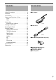
Contents Safety Precautions . . . . . . . . . . . . . . . . . . .2 Contents . . . . . . . . . . . . . . . . . . . . . . . . . . .9 Accessories . . . . . . . . . . . . . . . . . . . . . . . . .9 Names and Functions of Parts . . . . . . . . .10 Front . . . . . . . . . . . . . . . . . . . . . . . . . . .10 Rear . . . . . . . . . . . . . . . . . . . . . . . . . . .10 Connecting . . . . . . . . . . . . . . . . . . . . . . . .11 Connecting to a Device . . . . . . . . . . . . .11 Turning on the Power . . . . . .
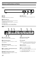
Names and Functions of Parts Front GRAPHICS INTERFACE Visualization Series MODE STATUS A B C A MODE C POWER Switch Do not open. Changing the settings will cause malfunction. Use this to turn on/off the main power supply of this unit. B STATUS Indicator This unit performs initialization when the power is turned on. The initialization takes about 15 seconds. The STATUS indicator shows the progress of the initialization with a dotted number. If the indicator shows "0." to "8.
Connecting Connecting to a Device Connect the device in the way as shown in the connection example below. Do not turn on the power until all connections are made. For details on the devices that can be connected to this unit, connection method and operation, please consult your authorized dealer. Refer to page 13 when mounting the rack.
䡵 When connecting to DLA-VS4800 (or DLA-SH7, DLA-SH4K) To DVI terminal Computer RS-232C cross cable or LAN, USB Cable (sold separately) DVI-D cable (sold separately) To RS-232C or LAN, USB terminal * Video source DC IN 12V LAN EXT. CONTROL USB DVI 1 IN REMOTE DVI 2 OUT IN DVI 3 OUT IN SYNC IN DVI 4 OUT IN OUT To DVI terminal DVI-D cable (sold separately) DLA-VS4800 (or DLA-SH7, DLA-SH4K) * To control using the computer, connect to any one of the terminals (RS-232C, LAN or USB).
Turning on the Power A Connect the power cord to the AC adapter Mounting the Rack You can mount this unit on the EIA 1U rack using the supplied rack mounting brackets. A Mount the rack mounting brackets on this unit using the four supplied bracket mounting screws M4 × 10 B Connect the AC adapter to this unit B Mount this unit on the rack ● The rack mounting screws are not supplied.
External Control It is possible to control this unit by connecting it to a PC using an RS232C cross cable (Dsub 9pin). The projector can be controlled by connecting it to a PC through the computer network with a LAN cable for control commands to be sent to the projector. ● To control using the computer, connect to any one of the terminals (RS-232C, LAN or USB). Do not use the terminals at the same time.
Data Format 䡵 Command format I Header ID SP Command SP Parameter 1 Item SP CR SP Parameter 2 Length Description Header 1 The beginning of data and data type ‘!’ (21) : Command to set or control ‘?’ (3F): Query command ID 1 Identification number of PK-VS4GD4G.
Tally Format 䡵 Tally (response) format Header ID SP SP Status Item Length SP Parameter 1 SP CR Parameter 2 Description Note Header 1 The beginning of tally ‘@’ (40): Response to query ID 1 Identification number of PK-VS4GD4G.
䡵 Tally (Response with normal termination) Header CR ID SP Status Item Length Description Note Header 1 The beginning of tally ‘@’ (40): Response to command ID 1 Identification number of PK-VS4GD4G.
Header Indicates the beginning and type of communication data.
Command (Detail) This section describes the commands that can be used with PK-VS4GD4G, Graphics Interface. 䡵 Offset Red: ‘I55’ Function Command Parameter Tally Sets the red offset to on/off and specifies the offset value if it is on. ‘!’ ‘1’ SP ‘I55’ SP ‘1’ SP ‘1’ SP ‘1234’ CR ‘?’ ‘1’ SP ‘I55’ SP ‘1’ CR Parameter 1 Specifies the channel number. ‘1’, ‘2’, ‘3’, ‘4’ : Channel number 1, 2, 3, 4 ‘0’ : All channels (Not available in a query command.) Parameter 2 Sets the red offset to On/Off.
䡵 Offset Green: ‘I56’ Function Command Parameter Tally Sets the green offset to on/off and specifies the offset value if it is on. ‘!’ ‘1’ SP ‘I56’ SP ‘1’ SP ‘1’ SP ‘1234’ CR ‘?’ ‘1’ SP ‘I56’ SP ‘1’ CR Parameter 1 Specifies the channel number. ‘1’, ‘2’, ‘3’, ‘4’ : Channel number 1, 2, 3, 4 ‘0’ : All channels (Not available in a query command.) Parameter 2 Sets the red offset to On/Off. ‘1’ : On ‘0’ : OFF Parameter 3 Specifies the offset value if the Parameter 2 is On.
䡵 Offset Blue: ‘I57’ Function Command Parameter Tally Sets the blue offset to on/off and specifies the offset value if it is on. ‘!’ ‘1’ SP ‘I57’ SP ‘1’ SP ‘1’ SP ‘1234’ CR ‘?’ ‘1’ SP ‘I57’ SP ‘1’ CR Parameter 1 Specifies the channel number. ‘1’, ‘2’, ‘3’, ‘4’ : Channel number 1, 2, 3, 4 ‘0’ : All channels (Not available in a query command.) Parameter 2 Sets the blue offset to On/Off. ‘1’ : On ‘0’ : OFF Parameter 3 Specifies the offset value if the Parameter 2 is On.
䡵 Gain Red: ‘I58’ Function Command Parameter Sets the red gain to on/off and specifies the gain value if it is on. ‘!’ ‘1’ SP ‘I58’ SP ‘1’ SP ‘1’ SP ‘1.0’ CR ‘?’ ‘1’ SP ‘I58’ SP ‘1’ CR Parameter 1 Specifies the channel number. ‘1’, ‘2’, ‘3’, ‘4’ : Channel number 1, 2, 3, 4 ‘0’ : All channels (Not available in a query command.) Parameter 2 Set the red gain to On/Off. ‘1’ : On ‘0’ : Off Parameter 3 Specifies the gain value if the Parameter 2 is On. Gain value range: 0 to 7.
䡵 Gain Green: ‘I59’ Function Command Parameter Sets the green gain to on/off and specifies the gain value if it is on. ‘!’ ‘1’ SP ‘I59’ SP ‘1’ SP ‘1’ SP ‘1.0’ CR ‘?’ ‘1’ SP ‘I59’ SP ‘1’ CR Parameter 1 Specifies the channel number. ‘1’, ‘2’, ‘3’, ‘4’ : Channel number 1, 2, 3, 4 ‘0’ : All channels (Not available in a query command.) Parameter 2 Set the green gain to On/Off. ‘1’ : On ‘0’ : Off Parameter 3 Specifies the gain value if the Parameter 2 is On. Gain value range: 0 to 7.
䡵 Gain Blue: ‘I5A’ Function Command Parameter Sets the blue gain to on/off and specifies the gain value if it is on. ‘!’ ‘1’ SP ‘I5A’ SP ‘1’ SP ‘1’ SP ‘1.0’ CR ‘?’ ‘1’ SP ‘I5A’ SP ‘1’ CR Parameter 1 Specifies the channel number. ‘1’, ‘2’, ‘3’, ‘4’ : Channel number 1, 2, 3, 4 ‘0’ : All channels (Not available in a query command.) Parameter 2 Set the blue gain to On/Off. ‘1’ : On ‘0’ : Off Parameter 3 Specifies the gain value if the Parameter 2 is On. Gain value range: 0 to 7.
䡵 Test Pattern: ‘I8D’ Function Command Parameter Tally Set the test pattern. ‘!’ ‘1’ SP ‘I8D’ SP ‘1’ SP ‘3’ CR ‘?’ ‘1’ SP ‘I8D’ SP ‘1’ CR Parameter 1 Specifies the channel number. ‘1’, ‘2’, ‘3’, ‘4’ : Channel number 1, 2, 3, 4 ‘0’ : All channels (Not available in a query command.) Parameter 2 Specifies the test pattern number.
Specifications Product name : Graphics Interface Model name : PK-VS4GD4G Digital video input format : 2048 × 1200, 2048 × 1080, 1920 × 1080, 1024 × 2400 (50/60 Hz, 8/10/12 bit (Input), 8/12 bit (Output)) DVI clock (Rx clock) : Up to 165 MHz (Single) : Up to 330 MHz (Dual) Input and output terminals Video input and output : DVI-D (Dual Link) 24 pins (supports 12-bit extended input) × 4, (does not support HDCP) REMOTE terminal (RS-232C) : D-sub 9 pins (male) × 1 EXT.
Dimensions 280 5.5 䡵 Top Rack mounting bracket (accessory) 䡵 Front 482 465 420 STATUS 43.6 MODE 31.8 GRAPHICS INTERFACE Visualization Series 10 380 䡵 Side 30 45 Front Rear 40 21.
GRAPHICS INTERFACE 取扱説明書 PK-VS4GD4 GRAPHICS INTERFACE Visualization Series MODE STATUS
安全上のご注意 絵表示について この取扱説明書と製品には、いろいろな絵表示が記載されています。これらは、製品を安全に正しくお使いいただき、お 客様や他の人々への危害や財産の損害を未然に防止するための表示です。絵表示の意味をよく理解してから本文をお読み ください。 この表示(文字含む)を無視して、誤った取り扱いをすると、人が死亡または重傷を負う可能 性が想定される内容を示しています この表示(文字含む)を無視して、誤った取り扱いをすると、人が傷害を負ったり、物的損害 の発生が想定される内容を示しています 絵表示の説明 䢇 注意(警告を含む)が必要な ことを示す記号 一般的注意 䢇 してはいけない行為(禁止行為)を 示す記号 禁止 ぬれ手禁止 o万一、次のような異常が発生したときは、そのまま 使用しない 火災や感電の原因となります。 ● 煙が出ている、へんなにおいがするなどの 異常のとき。 ● 画面が映らない、音が出ないなどの故障の 一般的注意 とき。 ● 内部に水や物が入ってしまったとき。 ● 落としたり、キャビネットが破損したと き。 ● 電源コードが傷んだとき。 (芯線の露出、 断線など)
o不安定な場所に置かない ぐらついている台の上や傾いた所に置かないでく ださい。落ちたりして機器の破損や故障の原因と なります。 oこの機器の上に重いものを置かない 重いものや本体からはみ出るような大きな物を置 くと、バランスがくずれて倒れたり落ちたりして、 けがの原因となることがあります。 o電源プラグはコードの部分を持って抜かない 禁止 電源コードを引っ張ると、コードに傷がつき、火 災・感電の原因となることがあります。プラグの 部分を持って抜いてください。 禁止 oぬれた手で電源プラグを抜き差ししない 感電の原因となることがあります。 禁止 ぬれ手禁止 o移動するときは、電源プラグや接続コー ドを外す 接続したまま移動すると、コードに傷がつき、火 災や感電の原因となることがあります。 o長期間使用しないときは、電源プラグを 抜く 安全および節電のため、電源プラグを抜いてくだ さい。 電源プラグ を抜く 電源プラグ を抜く 使用上のご注意 o通風孔をふさがない 保管および使用場所 o次のような場所に置かない 誤動作や故障原因になります。 ● 許容動作温度(10 ℃〜 35 ℃)範囲
目次 安全上のご注意 . . . . . . . 使用上のご注意 . . . . . . . 目次 . . . . . . . . . . . . . . . . 付属品 . . . . . . . . . . . . . . 各部のなまえとはたらき 前面 . . . . . . . . . . . . . . 背面 . . . . . . . . . . . . . . 接続する . . . . . . . . . . . . 機器に接続する . . . . . 電源を入れる . . . . . . . . . ラックに固定する . . . . . 外部制御 . . . . . . . . . . . . RS-232C 仕様 . . . . . TCP/IP 接続 . . . . . . . データフォーマット . . タリーフォーマット . . Header . . . . . . . . . . . ID . . . . . . . . . . . . . . . CR . . . . . . . . . . . . . . Error Code . . . . . . . .
各部のなまえとはたらき 前面 GRAPHICS INTERFACE Visualization Series MODE STATUS A B C A モード C 電源スイッチ 開けないでください。 設定を変えると故障の原因になります。 本機の電源をオン・オフします。 B ステータスインジケーター 本機の電源を入れると、初期化が実行されます。 初期化には約 15 秒かかります。 初期化の進行状況が、番号で表示されます。 起動中の初期化状況を "0" から "8" までの数字で表示して いきます。初期化が終了すると、本機の ID が表示されま す。ID 番号の工場出荷値は "1" です。 背面 D DC IN 12V E F LAN G EXT.
接続する 機器に接続する 下記の接続例のように、機器を接続できます。 接続が終わるまで、電源を入れないでください。 接続可能な機器や接続方法、操作については、お買い上げの販売店にお問い合わせください。 ラックに設置するときは、8 ページをご覧ください。 䡵 プロジェクター (DLA-VS2200/DLA-VS2000) に接続する場合 DVI 端子へ RS-232C クロス ケーブル、LAN ケーブルまたは USB ケーブル (別売) DVI -D ケーブル(別売) パソコン RS-232C 端子、 LAN 端子または USB 端子へ※ 映像ソース DC IN 12V LAN EXT.
䡵 DLA-VS4800 ( または DLA-SH7、DLA-SH4K) に接続する場合 DVl 端子へ RS-232C クロス ケーブル、LAN ケーブルまたは USB ケーブル (別売) DVl-D ケーブル(別売) パソコン RS-232C 端子、 LAN 端子または USB 端子へ※ 映像ソース DC IN 12V LAN EXT.
電源を入れる A 電源コードと AC アダプターに接続する ラックに固定する 取付金具(付属品)を使って、本機を EIA 1U 規格のラッ クに設置できます。 A 取付金具を本機に取り付け、ネジで固定する M4 × 10 B AC アダプターを本機に接続する B 本機をラックに取り付ける ● ラック取付用のねじは別売りです。 C 電源コードをコンセントに差し込む D 電源スイッチを入れる 8
外部制御 本機とパソコンを RS-232C クロスケーブル(D-sub9 ピン)で接続すると、本機を制御できます。 また、コンピューターネットワークを経由して、外部のパソコンと LAN ケーブルで接続し、制御コマンドを送ることで本機 を制御することもできます。 ● パソコンで制御するときは、RS-232C 端子、LAN 端子または USB 端子のいずれかひとつに接続してください。同時には使 用できません。 ● システムの管理者に相談するか、専門書などを読んで、ご理解した上でご利用ください。 RS-232C 仕様 ピン No.
データフォーマット 䡵 コマンドフォーマット I ID SP アイテム SP バイト長 SP CR SP 記述 注釈 ヘッダー 1 コマンドの先頭及び種類 ! (21) : 制御・設定コマンド ? (3F): クエリーコマンド(問合せ) ID 1 PK-VS4GD4 の識別番号 0 1 A a SP 1 ID とコマンドの区切り コマンド n コマンド SP 1 コマンドとパラメーターの 区切り パラメーター 1 SP パラメーター 1 パラメーターとパラメー ターの区切り (30) (31) to (41) to (61) to : 接続されている全ての PK-VS4GD4 9 (39): ID が合致する PK-VS4GD4 F (46) : ID が合致する PK-VS4GD4 f (66): ID が合致する PK-VS4GD4 (20): 区切り Ixx : コマンドコード (20): 区切り コマンドでパラメタ数 (0 から n) は変わります (20): 区切り パラメーター 2 n パラメーター SP 1 パラメーター
タリーフォーマット 䡵 タリーフォーマット(応答) ID SP アイテム SP バイト長 SP CR SP 記述 注釈 ヘッダー 1 タリーの先頭 @ (40): クエリーに対する応答 ID 1 PK-VS4GD4 の識別番号 0 (30) : 接続されている全ての PK-VS4GD4 1 (31) to 9 (39) : ID が合致する PK-VS4GD4 A (41) to F (46) : ID が合致する PK-VS4GD4 SP 1 ID とステータスの区切り ステータス 1 正常状態 SP 1 ステータスとパラメーター の区切り パラメーター 1 SP パラメーター (20): 区切り 0 (30): 正常状態のステータスコード (20): 区切り コマンドでパラメタ数 (0 から n) は変わります 1 パラメーターとパラメー ターの区切り (20): 区切り パラメーター 2 n パラメーター SP 1 パラメーターとパラメー ターの区切り パラメーター n n パラメーター コマンドでパラメタ数 (0 から
䡵 タリー(正常時のタリー) CR ID SP アイテム バイト長 記述 注釈 ヘッダー 1 タリーの先頭 @ (40): コマンドに対する応答 ID 1 PK-VS4GD4 の識別番号 0 (30) : 接続されている全ての PK-VS4GD4 1 (31) to 9 (39) : ID が合致する PK-VS4GD4 A (41) to F (46) : ID が合致する PK-VS4GD4 SP 1 ID とステータスの区切り ステータス 1 正常状態 CR 1 タリーの終端 (20): 区切り 0 (30): 正常状態のステータスコード (0D): コマンドの終端です 䡵 タリー(異常時のタリー) A CR ID SP アイテム バイト長 記述 注釈 ヘッダー 1 タリーの先頭 @ (40): コマンドに対する応答 ID 1 PK-VS4GD4 の識別番号 0 (30) : 接続されている全ての PK-VS4GD4 1 (31) to 9 (39) : ID が合致する PK-VS4GD4 A (41) to F (46)
Header 通信データの先頭および種類を示します。 䡵 Computer N PK-VS4GD4 (Graphics Interface) Character Hex Definition ‘!’ 21 PK-VS4GD3(Graphics Intergace) へのコマンド ‘?’ 3F PK-VS4GD3(Graphics Intergace) への問合せ 䡵 PK-VS4GD4 (Graphics Interface) N Computer Character Hex ‘@’ 40 Definition タリー(応答)データ ID 2 機以上の PK-VS4GD4 ユニットが 1 台のパソコンに接続されている場合、下記の数字を使って PK-VS4GD4 (Graphics Interface) を識別します。 それぞれの PK-VS4GD4 に別々の ID を設定すると、それぞれの PK-VS4GD4 ユニットを独立制御できます。 䡵 Assignable ID numbers ID Character (Hex) ID Character (Hex) 0 ‘
Command (Detail) このセクションでは、PK-VS4GD4 Graphics Interface で使用できるコマンドについて説明します。 䡵 Offset Red: ‘I55’ Function Command Parameter Tally 赤オフセットをオン / オフにし、オン時にオフセット値を指定します。 ‘!’ ‘1’ SP ‘I55’ SP ‘1’ SP ‘1’ SP ‘1234’ CR ‘?’ ‘1’ SP ‘I55’ SP ‘1’ CR Parameter 1 Specifies the channel number. ‘1’, ‘2’, ‘3’, ‘4’ : Channel number 1, 2, 3, 4 ‘0’ : All channels (Not available in a query command.) Parameter 2 Sets the red offset to On/Off.
䡵 Offset Green: ‘I56’ Function Command Parameter Tally 緑オフセットをオン / オフにし、オン時にオフセット値を指定します。 ‘!’ ‘1’ SP ‘I56’ SP ‘1’ SP ‘1’ SP ‘1234’ CR ‘?’ ‘1’ SP ‘I56’ SP ‘1’ CR Parameter 1 Specifies the channel number. ‘1’, ‘2’, ‘3’, ‘4’ : Channel number 1, 2, 3, 4 ‘0’ : All channels (Not available in a query command.) Parameter 2 Sets the red offset to On/Off. ‘1’ : On ‘0’ : OFF Parameter 3 Specifies the offset value if the Parameter 2 is On.
䡵 Offset Blue: ‘I57’ Function Command Parameter Tally 青オフセットをオン / オフにし、オン時にオフセット値を指定します。 ‘!’ ‘1’ SP ‘I57’ SP ‘1’ SP ‘1’ SP ‘1234’ CR ‘?’ ‘1’ SP ‘I57’ SP ‘1’ CR Parameter 1 Specifies the channel number. ‘1’, ‘2’, ‘3’, ‘4’ : Channel number 1, 2, 3, 4 ‘0’ : All channels (Not available in a query command.) Parameter 2 Sets the blue offset to On/Off. ‘1’ : On ‘0’ : OFF Parameter 3 Specifies the offset value if the Parameter 2 is On.
䡵 Gain Red: ‘I58’ Function Command Parameter 赤ゲインをオン / オフにし、オン時にオフセット値を指定します。 ‘!’ ‘1’ SP ‘I58’ SP ‘1’ SP ‘1’ SP ‘1.0’ CR ‘?’ ‘1’ SP ‘I58’ SP ‘1’ CR Parameter 1 Specifies the channel number. ‘1’, ‘2’, ‘3’, ‘4’ : Channel number 1, 2, 3, 4 ‘0’ : All channels (Not available in a query command.) Parameter 2 Set the red gain to On/Off. ‘1’ : On ‘0’ : Off Parameter 3 Specifies the gain value if the Parameter 2 is On. Gain value range: 0 to 7.
䡵 Gain Green: ‘I59’ Function Command Parameter 緑ゲインをオン / オフにし、オン時にオフセット値を指定します。 ‘!’ ‘1’ SP ‘I59’ SP ‘1’ SP ‘1’ SP ‘1.0’ CR ‘?’ ‘1’ SP ‘I59’ SP ‘1’ CR Parameter 1 Specifies the channel number. ‘1’, ‘2’, ‘3’, ‘4’ : Channel number 1, 2, 3, 4 ‘0’ : All channels (Not available in a query command.) Parameter 2 Set the green gain to On/Off. ‘1’ : On ‘0’ : Off Parameter 3 Specifies the gain value if the Parameter 2 is On. Gain value range: 0 to 7.
䡵 Gain Blue: ‘I5A’ Function Command Parameter 青ゲインをオン / オフにし、オン時にオフセット値を指定します。 ‘!’ ‘1’ SP ‘I5A’ SP ‘1’ SP ‘1’ SP ‘1.0’ CR ‘?’ ‘1’ SP ‘I5A’ SP ‘1’ CR Parameter 1 Specifies the channel number. ‘1’, ‘2’, ‘3’, ‘4’ : Channel number 1, 2, 3, 4 ‘0’ : All channels (Not available in a query command.) Parameter 2 Set the blue gain to On/Off. ‘1’ : On ‘0’ : Off Parameter 3 Specifies the gain value if the Parameter 2 is On. Gain value range: 0 to 7.
䡵 Test Pattern: ‘I8D’ Function Command Parameter Tally テストパターンを設定します。 ‘!’ ‘1’ SP ‘I8D’ SP ‘1’ SP ‘3’ CR ‘?’ ‘1’ SP ‘I8D’ SP ‘1’ CR Parameter 1 Specifies the channel number. ‘1’, ‘2’, ‘3’, ‘4’ : Channel number 1, 2, 3, 4 ‘0’ : All channels (Not available in a query command.) Parameter 2 Specifies the test pattern number.
仕様 品名 : グラフィックスインタフェース 型名 : PK-VS4GD4 デジタルビデオ入力形式 : 2048 × 1200, 2048 × 1080, 1920 × 1080, 1024 × 2400 (50/60 Hz、8/10/12 ビット ( 入力 )、8/12 ビット ( 出力 )) DVI クロック (Rx クロック) 入出力端子 映像入出力 REMOPTE 端子 (RS-232C) : 165 MHz まで(シングル) : 330 MHz まで(デュアル) : DVI-D (デュアルリンク)24 ピン (12 ビット拡張入力に対応)× 4、(HDCP に未対応) : D-sub 9 ピン(オス)× 1 EXT.
外形寸法 280 5.5 䡵 上面 䡵 前面 482 465 420 STATUS 43.6 MODE 31.8 GRAPHICS INTERFACE Visualization Series 10 380 䡵 側面 30 45 前面 後面 22 40 21.
PK-VS4GD4G PK-VS4GD4 GRAPHICS INTERFACE © 2013 JVCKENWOOD Corporation Printed in Japan 1303TTH-SW-X