
OperationManual

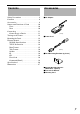
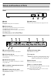
Table Of Contents

10
Front
A MODE
Do not open.
Changing the settings will cause malfunction.
B STATUS Indicator
This unit performs initialization when the power is turned on.
The initialization takes about 15 seconds.
The STATUS indicator shows the progress of the initialization
with a dotted number.
If the indicator shows "0." to "8." in order and finally "1"
(factory default unit ID), the unit is in working condition.
C POWER Switch
Use this to turn on/off the main power supply of this unit.
Rear
D Power Input Terminal
Connect the supplied AC adapter to this terminal.
E LAN Terminal (RJ-45)
This unit can be controlled by connecting it to a computer
using a LAN cable.
F USB Terminal (Type B)
This unit can be controlled by connecting it to a computer
using a USB cable.
G EXT. CONTROL Terminal (D-sub 15 pins)
This is an extension terminal.
H REMOTE Terminal (D-sub 9 pins)
This unit can be controlled by connecting it to a computer
using a RS-232C cross cable.
I SYNC IN Terminal (BNC)
Input terminal for sync signals.
J Cooling Fan
K Earth Terminal
Connect the earth wire to this terminal.
L DVI 1 to 4 Terminals (DVI-D)
Names and Functions of Parts
MODE
STATUS
GRAPHICS INTERFACE
Visualization Series
BAC
REMOTEEXT. CONTROL
DC IN 12V
IN OUT
DVI 4
IN OUT
DVI 3
IN OUT
DVI 2
IN OUT
DVI 1
SYNC
IN
USBLAN
D E FGH
I
CAUTION: Do not block the cooling fan with papers, cloth or
soft cushions. Doing so may cause heat to trap
inside the unit and result in fire or malfunction.
IN : Input terminal for video signals. Connect it to the video
source output using a DVI cable.
OUT : Output terminal for video signals. Connect it to the
projector using a DVI cable.