® is a registered trademark owned by VICTOR COMPANY OF JAPAN, LTD. is a registered trademark in Japan, the U.S.A., the U.K. and many other countries. © 2003 VICTOR COMPANY OF JAPAN, LIMITED ® VICTOR COMPANY OF JAPAN, LIMITED Printed in Japan LST0124 SA-DV6000 INSTRUCTIONS Serial No. Model No. SA-DV6000 For Customer Use: Enter below the Serial No. which is located on the case. Retain this information for future reference. LST0124 This instruction book is made from 100% recycled paper.
I 19. 18. 17. 16. 13. 14. 15. 12. 11. 10. 9. 8. 7. 5. 6. 1. 2. 3. 4. Read all of these instructions. Save these instructions for later use. All warnings on the product and in the operating instructions should be adhered to. Unplug this appliance system from the wall outlet before cleaning. Do not use liquid cleaners or aerosol cleaners. Use a damp cloth for cleaning. Do not use attachments not recommended by the appliance manufacturer as they may cause hazards.
Safety Precautions E-2 Caution Where there are strong electromagnetic waves or magnetism, for example near a radio or TV transmitter, transformer, motor, etc., the picture may be disturbed. In such case, please keep the apparatus away from the sources of the disturbance. In order to keep the best performance and furthermore for electromagnetic compatibility. Use the PC Card which acquired a CE mark. The Adobe Acrobat Reader is required to view PDF files.
Contents E-4 ● Be sure to turn the VCR’s power supply OFF before the SA-DV6000 is attached to the VCR. ● Be sure to turn the VCR’s power supply OFF before inserting or removing CF (Compact Flash) cards, etc., into and from the VCR. Inserting or removing cards while the VCR’s power supply is turned ON can result in corruption of the recorded sections of the card or damage to the card itself.
OUT IN LINE MONITOR OUT DC12V VIDEO IN IN SERIAL REMOTE TIME CODE B-Y COMPONENT R-Y DV IN/OUT SYNC IN Y IN REC OUT OUT REMOTE2 PLAY OUT IN MONITOR OUT AUDIO CH 1/3 CH 2/4 TIMER OFF OUT REMOTE1 LAN INTERNET 2.
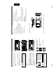
2 1 5 LAN Connector Connect LAN cable here. 6 LINK LED Lights up when network is connected. 2 EJECT Button Push to eject the card. 3 Mounting screw holes Used to install this product to the rear panel of the BR-DV6000 with screws. E-8 4 Connector Connects by pushing in the connector for connecting to the VCR main unit. 3 6 5 1 PC Card Slot Insert LAN card, CompactFlash card, etc. here. Please don’t touch the metal parts other than the panel.
When the power is turned on and the initialization process takes place, the card status indicators shown on the left will blink. E-10 To remove the card, turn the BR-DV6000’s power off, and then press the Eject button 5 to eject the card. CAUTION NOTE 4 Confirm the card status. Make sure that the correct card status indicator that matches the type of card you inserted is displayed on the LCD of BRDV6000. ❈ The card status can be confirmed when BR-DV6000 LCD screen is in enlarged display mode.
© 2003 VICTOR COMPANY OF JAPAN, LIMITED is a registered trademark owned by VICTOR COMPANY OF JAPAN, LTD. is a registered trademark in Japan, the U.S.A., the U.K. and many other countries.
2 TOP PAGE can be customized ...................................................................................................................................................... 61 Connecting Windows Media Player ............................................................................................................................................... 62 Connecting QuickTime Player .........................................................................................................................
IN IN SERIAL REMOTE TIME CODE B-Y COMPONENT R-Y DV IN/OUT SYNC IN Y IN REC OUT OUT REMOTE2 PLAY IN OUT MONITOR OUT AUDIO CH 1/3 CH 2/4 TIMER OFF OUT REMOTE1 LAN terminal LAN 48k L 20 M 10 S 0 OVER dB OVER SP222min W 01/02/03 Y/C AM 01:23:45 INS ‰ CF CF e : CF memory card : LAN card or builtin LAN enabled : Flashes during initialization Card status display 4 Press the EJECT button of SA-DV6000 and remove the card. Turn off the BR-DV6000 power.
There is possibility of unit malfunction. Contact your nearest JVC dealer. Card is inserted in Network Pack but transmission is not available. CF memory card is being recorded with data. CF memory card is inserted in Network Pack. Video/audio data is being sent via LAN card. LAN card is inserted in the Network Pack, or built-in LAN is enabled. mum level. (The indicator is for reference. The value does not value from 5 to 0, 5 means maximum level and 0 means mini- information on LCD of the BR-DV6000.
PAGE BACK PRE FILTER ✩ STREAM TYPE AD1 AD2 for WMP for QT FRAME SIZE 320 × 240 160 × 120 MAX MID MIN MAX MID MIN 12.5 5 5 25 12.5 12.5 12.5 5 5 25 12.5 5 12.5 5 5 25 12.5 5 5 5 1 12.5 12.5 5 1 1 1 12.5 5 5 FRAME SIZE 320 × 240 160 × 120 MAX MID MIN MAX MID MIN 15 10 7.5 30 15 10 15 10 7.5 30 15 10 15 7.5 5 30 15 7.5 7.5 5 3 15 10 7.5 3 1 1 10 7.5 5 8 → OVER Pressing the SET button or SEARCH– button returns to the NETWORK PACK CONFIG menu screen.
Setting TC 0 0 : 0 0 : 0 0 . 0 0 E NC OD E S E T UP F RAME S I Z E 320x240 B I T RA T E 384kb / s MA X F RAME RA T E M I D S T R E AM T Y P E for WMP P AGE BACK Setting TC 0 0 : 0 0 : 0 0 . 0 0 ( WMP u n d e r 8 ) ( CF V i e w e r ) N E TWOR K P A CK C ON F I G NE T WOR K MA I N S E T UP . . EN CODE S E T UP . . MPE G R EC TR I G MOV I E CL I P S E T UP . .
PASSWORD DIRECTORY ✩ ✩ PAGE BACK PAGE BACK PASSIVE MODE USER NAME ✩ ✩ MACHINE NAME ✩ FTP Client ✩ NAME SERVER ✩ GATE WAY 12 → OVER Pressing the SET button or SEARCH– button returns the unit to the NETWORK MAIN SETUP screen. Pressing the SET button or SEARCH– button returns the unit to the NETWORK SETUP screen. Selects ON/OFF of the PASSIVE mode. If data connection cannot be established with the PASSIVE mode set to OFF, set the PASSIVE mode to ON.
ON OFF SETUP ON WEB Pressing the SET button or SEARCH– button returns to the NETWORK MAIN SETUP menu screen. Displays the FTP PASSWORD input screen. (4 ~ 8 alphanumerical characters) Used when uploading USER PAGE. [Default setting: sa-dv] Caution Lastly, enter the new password again when “CONFIRM NEW PASSWORD” is displayed. Next, enter the new password when “ENTER NEW PASSWORD” is displayed. (When setting the password for the first time, enter the factory set value as the OLD PASSWORD.
TC 0 0 : 0 0 : 0 0 . 0 0 M ENU RE SE T . . ( WMP u n d e r 8 ) ( C F V i e we r ) N E TWOR K P A CK C ON F I G NE T WOR K MA I N S E T U P . . EN CODE S E T U P . . MPE G R EC TR I G MOV I E CL I P S E T U P . . MENU R E S E T E X E CU TE PAGE B ACK NETWORK PACK CONFIG menu screen RESET CH-2/4 BR-DV6000 PROFESSIONAL BLANK ( ) button CH-1/3 REC LEVEL CUE UP SEARCH+ REW REC STOP PLAY AUDIO INPUT COUNTER MONITOR OUTPUT SELECT DV CH-1/2 CTL L TC LINE MIX MIX Y/C CH-3/4 R UB (CPN) EJECT A.
TC 0 0 : 0 0 : 0 0 . 0 0 . ENCODE. SET . FRAME. S I ZE NNNNNNN3 2 0 x 2 4 0 . B I T. RATE. NNNNNNNNNN3 8 4 K . . MAX. FRAME. RATENNNNN M I DNNNN STREAM. TYPE NNNNNNNNfor WMP N PRE F I L TER NNNNNNNN AD1 NN PAG.E BACKNNNNNNNNNNNNNNNNNN TC 0 0 : 0 0 : 0 0 .
LAN connections Wired LAN SET CH-1/3 CH-2/4 REC LEVEL CUE UP SEARCH+ RESET OFF BR-DV6000 PROFESSIONAL REW REC STOP PLAY OPERATE AUDIO INPUT COUNTER MONITOR OUTPUT SELECT CTL L CH-1/2 DV TC MIX MIX LINE R CH-3/4 Y/C UB (CPN) EJECT A.DUB LOCAL REMOTE FF PAUSE * For the PC settings when using a LAN card, refer to the instruction manual included with the LAN card. * Up to 10 clients can access at the same time.
Hub DISP SET PHONES RESET CUE UP SEARCH+ CH-1/3 CH-2/4 REC LEVEL BLANK MENU HOLD SEARCH– BR-DV6000 PROFESSIONAL REC REW PLAY STOP AUDIO INPUT COUNTER MONITOR OUTPUT SELECT CH-1/2 DV CTL L TC MIX MIX LINE R CH-3/4 Y/C UB (CPN) EJECT A.DUB LOCAL REMOTE FF PAUSE Set the same domain IP ADDRESS 192. 168. 100. XXX SUBNET MASK 255. 255. 255.
PHONES RESET CUE UP SEARCH+ CH-1/3 CH-2/4 REC LEVEL BLANK SET HOLD DISP MENU SEARCH– REW REC STOP PLAY OPERATE AUDIO INPUT COUNTER MONITOR OUTPUT SELECT DV CH-1/2 CTL L TC LINE MIX MIX Y/C CH-3/4 R UB (CPN) EJECT A.DUB LOCAL REMOTE FF PAUSE OFF ON abcdef 2 192. 168. 100. 101 255. 255. 255. 000 BR-DV6000 PROFESSIONAL PROXY SERVER DHCP SERVER IP ADDRESS SUBNET MASK * For the PC settings when using a LAN card, refer to the instruction manual included with the LAN card.
192. 168. 100. 102 255. 255. 255. 000 OFF OFF abcdef 2 192. 168. 100. 103 255. 255. 255. 000 IP ADDRESS SUBNET MASK DHCP WLAN AD HOC MODE WLAN ESS ID WLAN CH IP ADDRESS SUBNET MASK Set the same domain 192. 168. 100. XXX 255. 255. 255. 000 192. 168. 100. 104 255. 255. 255. 000 IP ADDRESS SUBNET MASK MENU HOLD SEARCH– SET DISP RESET CUE UP SEARCH+ CH-1/3 CH-2/4 REC LEVEL BLANK EJECT A.
Using LAN card/LAN terminal Streaming and Capturing Video INPUT SELECT switch of the VTR to “DV”. 28 When performing a different type of transmission, switch the PB/DV IN setting in the SYSTEM menu of the VTR. In addition, set the Memo Guide. of the video on the computer. Instructions for using this mode can be found in the Trigger mode function of the Streamproducer Users ● OFF – This disables the VTR operators’ control of the PC recording. VTR operation is as normal.
H 30 20 M 10 S 0 VA SYNC ‰ Displayed only when setting MPEG REC to SPLIT. Set to SPLIT TC 0 0 : 0 0 : 0 0 . 0 0 ( WMP u n d e r 8 ) ( C F V i e we r ) C F REC : P U S H ' S E T ' N E TWOR K P A CK C ON F I G NE T WOR K MA I N S E T U P . . EN CODE S E T U P . . MPE G R EC SPL I T MOV I E CL I P S E T U P . .
Preparing for CF card recording SET CUE UP SEARCH+ RESET CH-2/4 TC 0 0 : 0 0 : 0 0 . 0 0 M O V I E C L I P S E TU P DE L E T E A L L CA N CE L CA N CE L F OR MAT REPEAT RP E AT P L A Y CA P T U R E . . F I L E S E ND PAGE B ACK MOVIE CLIP SETUP menu screen Set to EXECUTE Flashing display during formatting F ORMAT TC 0 0 : 0 0 : 0 0 . 0 0 M O V I E C L I P SE T U P DE L E T E A L L CA N CE L E X E CU T E F OR MAT R EP E A T P L A Y REPE AT CA P T U R E . .
MIC Mini M 10 S 0 OVER SP222min 01/02/03 PLAY 30 20 10 S 0 F OVER dB OVER M VA SYNC CF memory card remaining warning SP222min W 01/02/03 Y/C AM 01:23:45 INS H ‰ CF e 12 34 34 10 CF REMAIN 60SEC! 40 LCD screen Displayed only when setting MPEG REC to SPLIT. Set to SPLIT TC 0 0 : 0 0 : 0 0 .
Specifying the range of a DV tape and recording to a CF memory card OU T P O I N T 5. 4. Specify the range to record to CF memory card. q Operate the VTR and press the SET button when the video position to start recording appears in the LC screen. ● The time code of the position to start recording appears below the IN POINT display and the cursor (t) will move to OUT POINT SET. ● To accurately specify the position to start recording, use pause, frame advance function, etc.
M O V I E C L I P SE T CA N CE L DE L E T E A L L CA N CE L F OR MAT REPE AT RE P E A T P L A Y CAP TURE . . F I L E S E ND PAGE BACK MOVIE CLIP SET menu screen TC 0 0 : 0 0 : 0 0 . 0 0 clip file to the latest clip file. ( WMP u n d e r 8 ) ( C F V i e w e r ) Memo the SET button. Press the DISP (6) or BLANK (7) button, selecting the desired mode and press Move the cursor (t) to REPEAT PLAY and press the SET button. Form the NETWORK PACK CONFIG menu, select MOVIE CLIP SET.
PAGE BACK The BIT RATE used for recording is displayed. 85k PHONES HOLD CUE UP SEARCH+ RESET CH-2/4 BR-DV6000 PROFESSIONAL REW REC STOP PLAY (☞ page 9) PEAT”, repeat playback is performed. CLIP SETUP screen is set to “RE- ● When REPEAT PLAY in the MOVIE not a malfunction. 40 return to the MOVIE CLIP screen. \ Selecting PAGE BACK during playback or pausing and press the SET button will When all remaining clips are played back, the unit pauses at the beginning of the played back clip.
Protecting a clip file on a CF memory card CLIP SETUP menu screen, protected ● When executing FORMAT in the MOVIE CL I P R /W 09 : 0 0 : 00 R /W 09 : 3 0 : 25 R /W 10 : 1 0 : 55 R /W 11 : 0 0 : 00 REV I E W D E LE T E P ROT E C T F T P SE N D S E L EC T OF F F T P SE N D PAGE B AC K MO V I E C L I P mc 0 0 0 5 . a s f R /W CLIP FUNCTION screen Clip number MO V I E mc 0 0 0 5 . a s f 02 / 03 / 02 mc 0 0 0 6 . a s f 02 / 03 / 02 mc 0 0 0 7 . a s f 02 / 03 / 02 mc 0 0 0 8 .
OUT IN LINE MONITOR OUT DC12V VIDEO IN R-Y DV IN/OUT SYNC IN Y IN SERIAL REMOTE TIME CODE B-Y IN REC OUT OUT REMOTE2 PLAY OUT IN MONITOR OUT AUDIO CH 1/3 CH 2/4 TIMER OFF OUT REMOTE1 LAN CF memory card slot(s), CF card reader is not required. * If the PC is equipped with PCMCIA Launch Explorer, etc., and open the recorded clip file in ASF format. 2. 44 Video and audio files (clip files) in CF memory cards can be appended to email as attachment files.
Transferring multiple clips on a CF memory card to a server 3. 2. 1. CL I P R /W 09 : 0 0 : 00 R /W 10 : 0 0 : 00 R /W 11 : 0 0 : 00 R /W 12 : 0 0 : 00 M O V I E C L I P S E TU P DE L E T E A L L CA N CE L CA N CE L F OR MAT REPEAT MODE REPEAT CA P T U R E . . F I L E S E ND PAGE B ACK MOVIE CLIP SETUP screen REV I E W D E LE T E P ROT E C T F T P SE N D S E L EC T OF F F T P SE N D PAGE B AC K MO V I E C L I P mc 0 0 0 4 . a s f R /W CLIP FUNCTION screen MO V I E mc 0 0 0 1 .
Controlling the BR-DV6000/SA-DV6000 via a network NETWORK SETUP page 48 Item Setting Description The AD-HOC mode can be set. ● WLAN Channel can be set. ● Select the region of use using the COUNTRY setting. USA: U.S., EU: Europe, FRN: France, SPN: Spain, JPN: Japan IBSS AHDM OFF 1 CH : 10 CH : 14 CH AD-HOC MODE WLAN Channel When Change is selected, settings can be made in the LEAP Server Account Setup screen.
Select ON/OFF of the PASV mode. If data connection cannot be established with the PASV mode set to OFF, set the PASV mode to ON. Directory Passive Mode 50 For transferring clips on a CF memory card to a server, see page 60. Memo Input the password for logging onto the FTP server. Input the save folder of the FTP server. Password Input the host name of the FTP server. Input the user name for logging onto the FTP server. User Name Content Machine Name Item the input settings.
PORT SETUP page 8554 554 The Streamproducer RTSP port number can be set. (1 ~ 32767) Quick Time RTSP port number can be set. (1 ~ 32767) RTSP (for Streamproducer) RTSP (for Quick Time) — REV REC-PAUSE REC — FWD REC — REC-PAUSE — REC REW PLAY — FF REC REC STOP Previous mode displayed correctly depending on the environment. In this case, access by specifying the new port using a browser. (☞ operation 7.
ENCODE PARAMETERS Setting 320 × 240 160 × 120 56K (bps) 128K (bps) 256K (bps) 384K (bps) 512K (bps) MAX MID MIN Item Frame Size Bit Rate Frame Rate indicates default factory setting. Setting range Screen selection Description confirm setting. Click the OK icon to pull-down menu. Select the setting from the Setting FRAME SIZE 320 × 240 160 × 120 MAX MID MIN MAX MID MIN 12.5 5 5 25 12.5 12.5 12.5 5 5 25 12.5 5 12.5 5 5 25 12.5 5 5 5 1 12.5 12.5 5 1 1 1 12.
Network remote control STREAMCAPTURE (Playing back video/audio using a PC and saving to file) STREAMCAPTURE (Playing back video/audio using a PC and saving to file) Click when transmitting color bars rather than video from SA-DV6000. (Video from SA-DV6000 will be displayed in the video display of the Streamcapture screen. Color bars will not be displayed.) CAST-BARS MUTE Click to turn on/off the mute setting. When on, the playback sound will be muted.
STREAMCAPTURE (Playing back video/audio using a PC and saving to file) CASTBARS button CASTTRIG. button CAST-TRIG. Button. (☞ page 57) synchronizing to the button operations of BR-DV6000, click the When transmitting video/audio from SA-DV6000 to another PC by connected. In this case, the connection with the receiving side will be dis- turn off the CAST-VIEW/CAST-BARS button. ● To stop the transmission of video from SA-DV6000 / color bars, of video from SA-DV6000.
Transferring clips on a CF memory card to a server ● 60 Click the FTP button to transfer the selected clips to the server. Select the checkboxes of the file numbers to transfer. (Multiple selections allowed) Select the clips to transfer. Click FTP SEND SETUP on the left side of the Stramcorder screen to display the FTP SEND SETUP screen as shown above. Operating the FTP SEND SETUP screen \ To cancel transfer, click the CANCEL button. 3. 1. 2.
Set the IP address of the VTR. Memo When completed with setting, select OK to establish connection. # → HTTP Port number set in “for Media player” * → IP address of VTR http://***.***.***.***:####/asf Use QuickTime Player. (☞ page 63) ● WMP for Mac OS not supported. stop playback on Media Player and try again. 62 ● If there is a lag between the video and audio, set the sampling frequency of input and the audio mode of BR-DV6000 to match, 5. 4. The following dialog box will appear.
CH-2/4 CANCEL EXECUTE REW REC STOP PLAY OPERATE LOCAL REMOTE FF PAUSE Troubleshooting Both IN POINT and OUT POINT have not been set. STOP button was pressed during capturing. Clips on the CF card are being transferred to a server. IN/OUT POINT NOT SET! CAPTURE STOP! WAIT A MINUTE, PLEASE! function may occur as a result. Description 64 Press the SET button to return to the NETWORK PAC CONFIG menu screen. → OVER 36 Specified range of the DV tape is being recorded.
42 –– 12 12 13, 52 13, 52 13, 52 13, 52 12 13 14 14 14 –– 12 To delete the clip file, remove the protection. Check the CF memory card. Set DHCP in the NETWORK SET menu screen to OFF when using the AD HOC mode. Set WLAN AD MOC MODE in the NETWORK SET menu screen to OFF when using DHCP server. Set an unused port. Set an unused port. Set an unused port. Set an unused port. Set a value within the setting range. Set using 10 or 26 characters. Set using 3 or more / 4 or more characters.
Form of communication via an access point. ● Infrastrucre (wireless LAN) 68 A mode for direct communication without passing through an access point. ● Ad hoc mode (wireless LAN) Network identification name used by wireless LAN. The name is used to distinguish other wireless LAN devices. ● ESS-ID (wireless LAN) doubling. → OVER may reduce throughput or the quality of communication. When setting, check the settings of surrounding access points, etc.
About IP address/proxy server This IP address is referred to as “local IP address”. addresses can be used freely within a network. In an environment not connected to the Internet (within a household, within a company, etc.), separate IP Normally, the global address is assigned by the IS provider. Class B Class C 128~191 192~223 Application (number of PCs structuring the network) For small-scale networks (max. approx. 120 units) For medium-scale networks (max. approx.