TK-C655/TK-C676 DOME TYPE CAMERA DOME TYPE CAMERA TK-C655 TK-C676 INSTRUCTIONS (B) ailand A-H LWT0200-001A-H TK-C676-C655 in_LWT0200-001A-H 49 04.6.
These are general IMPORTANT SAFEGUARDS and certain items may not apply to all appliances. IMPORTANT SAFEGUARDS 1. 2. 3. 4. 5. 6. 7. 8. 9. 10. 11. 12. 13. 14. 15. 16. 17. 18. 19. Read all of these instructions. Save these instructions for later use. All warnings on the product and in the operating instructions should be adhered to. Unplug this appliance system from the wall outlet before cleaning. Do not use liquid cleaners or aerosol cleaners. Use a damp cloth for cleaning.
Thank you for purchsing this product. (These instructions are for TK-C655E, TK-C676E) Before beginning to operate this unit, please read the instruction manual carefully in order to make sure that the best possible performance is obtained. Contents Introduction Features ............................................................................................................................................................................. Provided Accessories .............................................
Introduction Features 䡵 DSP with a wide dynamic range Even objects that have a large difference in brightness can be monitored clearly. 䡵 Optical zoom lens (TK-C655 only) Detailed surveillance can be performed with the approx. x25 optical zoom lens. 䡵 Day/night surveillance When the light is low, the camera pictures can be switched automatically to black and white pictures. The camera is also compatible with IR illumination (wavelength 850 nm to 880 nm).
Safety Precautions WARNING: TO REDUCE THE RISK OF FIRE OR ELECTRIC SHOCK, DO NOT EXPOSE THIS APPLIANCE TO RAIN OR MOISTURE. AVERTISSEMENT: POUR EVITER LES RISQUES D'INCENDIE OU D'ELECTROCUTION, NE PAS EXPOSER L'APPAREIL A L'HUMIDITE OU A LA PLUIE. WARNING CAUTION • Install the unit on a strong and stable surface. This unit has been designed to revolve at high speed. Due to its weight (about 2.4 kg) and the vibrations it may be subjected to, the camera must be mounted to a sturdy and stable material.
Introduction Precautions for Correct Operation ● To save energy, turn the system off whenever it is not in use. ● This camera has been designed for indoor use. It cannot be used outdoors. ● This camera has been designed to be hung from a ceiling, do not install it in an upright position on a surface or at an angle, as this may cause a malfunction or a noticeable shortening of its service life. ● Do not install or use the camera in the following locations. • In a place exposed to rain or water.
䡲 Note on consumable parts The following parts are consumable and should be replaced after a certain number of hours or a count of operations. The service lives given below are only typical values. They may vary depending on the operating environment and conditions. Note that the replacement of consumable parts is chargeable even when they are replaced before the termination of the warranty period.
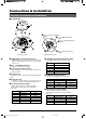
Connections & Installation Controls, Connectors and Indicators■ Camera body 䡵 Ceiling Mount 0 Cover 8 7 9 6 1 of alarm output terminal 9 Pin (CN24) 1 of CONTROL terminal 8 Pin (CN22) 1 of ALARM I/O terminal 7 Pin (CN23) 1 5 2 6 Pin 1 of alarm input terminal 34 (CN26) (Terminal Pin Layout) (Connector side) 1 [VIDEO OUT] Coaxial Cable Connectors Output connector of a composite video signal (1 V(p-p)) with an output impedance of 75 Ω, to be connected to a switcher, etc.
& % # ^ $ * ⁄ ! @ # (Setting switch side) 0 Cover For protection against water drips. Slit the rubber cap on this cover and pass the cable through the slits. P. 16 ☞ ! Camera Connector (Female) Connect to ^, the Male Connector on the camera. ( ) ^ Connector (Male) Connect to !, the Female Camera Connector on the Ceiling Mount. & Drop Prevention Wire Attach this wire to the Drop Prevention Hook Ceiling Mount.
Connections & Installation A Multi-Drop Communication System 䡵 A system that employs the RM-P2580 as the controller The following figure shows a system that can accommodate up to eight cameras. (100 positions can be preset per camera.) Control signal cable TK-C655/ TK-C676 Camera 1 Observe the following points when connecting components together: • Turn all the components off before proceeding. • Read the instruction manuals of all components before proceeding.
䡵 A system that does not employ the RM-P2580 as the controller MEMO Be sure to terminate the control signal cable at both ends. The cables (length of stub) connecting pieces of non-terminated equipment (cameras or controllers) must be as short as possible. If the length of stub is too long, control precision may suffer. ● When the controller is not located at the end of a system.
Connections & Installation Point-to-Point Communication System The following illustration shows a system in which a remote control unit (or a similar piece of equipment) controls a single camera. Video out Control signal cable AC 24 V power supply ( CAUTION Monitor Switch 4 : OFF (Point to Point) Switch 8 : ON (Terminated 110Ω) Controller Observe the following points when connecting components together: • Turn all the components off before proceeding.
Use twisted-pair cables for the connections. ●Duplex When the camera is controlled using the full duplex protocol, set Switch 5 to OFF. ●Simplex When the camera is controlled using the simplex transmission protocol, set Switch 5 to ON. Camera RX+ Controller TX+ Camera RX+ Controller TX+ RX– TX– RX– TX– TX+ RX+ TX– RX– Two wires must be connected. Four wires must be connected.
Connections & Installation Switch Settings Set the switches on the Ceiling Mount before installing the camera. Settings vary according to configuration of the system used. 䡵 Setting switches DISP PROTOCOL(1) PROTOCOL(2) SYNC Invalid (Set to OFF) RX TERM 8 7 6 5 4 3 2 Invalid (Set to OFF) O F F 1 Switch 1 Switch 2 Switch 3 Switch 4 Switch 5 Switch 6 Switch 7 Switch 8 ● Switches 1, 2 ● SYNC (Switch 6) These switches must be set to OFF.
䡵 Setting switches 456 Figure of 1 456 901 23 Figure of 10 78 901 23 78 ● Machine ID When using a multi-drop system with a remote control unit such as a RM-P2580, the machine IDs need to be set for each camera. Machine IDs are used to identify each of the multiple cameras connected to the RM-P2580. Set the machine IDs according to the corresponding VIDEO INPUT terminal numbers on the RM-P2580. “0” “1” 78 901 1.
Connections & Installation Cable Connections Connect cables to the Ceiling Mount as described below. 1. Make a 90 mm diameter hole in the ceiling. Connect the cables. Connect the cables to the terminals on the Ceiling Mount. The four connection cables should consist of a AC 24V power cable, a coaxial cable, a control signal cable and an alarm signal cable. Diameter 90 mm 2. 4. Control signal cable Remove the cover from the Ceiling Mount.
Coaxial cable ☞ P. 8 Alarm signal cables Connecting a RG-59 coaxial cable. Alarm output terminals (CN24) Connect the provided 4P Alarm cable to these terminals. If a RG-11 coaxial cable is used it cannot be connected directly to the terminal board. To use such a cable, connect a RG-59 cable to the camera and then connect the RG-11 cable to the RG-59 cable. Alarm input/output terminals (CN23) Treat the extremity of the coaxial cable as shown below before connecting it.
Connections & Installation Attaching the Ceiling Mount To a ceiling slab or channel 1. Attaching a safety wire. Attach a safety wire to the ceiling mount and to the ceiling slab or channel to prevent the unit from dropping. First attach the safety wire to the ceiling mount by passing the wire through the safety wire hole (see the diagram on the left). Safety wire hole MEMO ● Connect the wire so that it can be insulated from the ceiling strucCeiling mount Rubber packings (Four on each side) ture.
Ceiling Mount Lock screw 2. Ensure that the lock screw is loose. The camera cannot be attached properly if the lock screw of the Ceiling Mount is too tight. Camera 3. Camera clamping bracket Fit the camera. Check the position of the camera clamping bracket and that of the lock screw, and fit the camera onto the ceiling mount. Camera clamping bracket 4. Rotate the camera. Make sure that the camera is horizontal, then turn the camera clockwise until it stops.
Setting Up the Camera Using an RM-P2580 Setup Procedure In systems using an RM-P2580 remote control unit, the menus for use during camera setup can be displayed on the remote control unit. (Please refer to the instructions for RM-P2580.) 1. Power switch (Rear panel) MENU button SET button Set the Power switch on the rear panel of the RMP2580 to ON. The POWER lamp lights up.
Menu Screen Flow The menu screens are arranged in a hierarchical structure as shown below. Refer to the respective reference pages for the details of each menu. Normal screen S E T UP POS I T I ON S E T UP . . CAMERA . . CON T RO L UN I T . . ☞ P.22 – – CAMERA F UNC T I ON 1 – – V . PHASE 0 POS . T I T L E L OC . UP - L FL I P D I G I TAL VAR . P / T SPEED ON EASY AF OFF D . Z OOM M A X X 2. V. SHARPNESS N OR MA L T I LT L IMIT 5 ° PR I V A T E MA S K . . TK-C676 only CAMERA FUNCTION1 screen ☞ P.
Setting Up the Camera Using an RM-P2580 CAMERA FUNCTION1 Screen This screen sets up the functions of the camera itself. Item V. PHASE POS. TITLE LOC. FLIP VAR. P/T SPEED EASY AF Function & Setting Initial Value This adjusts the vertical synchronization to those of other cameras when a selector switch for the synchronizing system on the Ceilling Mount is at LL. (50 Hz power region only.) Setting values : –156 to 0 to 156 Sets the location of the position title and area title in the monitor.
Item Function & Setting Initial Value PRIVATE MASK.. This function grays out sections that are not to be displayed in the monitored picture area. The grayed out section moves accordingly when the camera is panned, tilted or when the zoom is adjusted. P.32, “PRIVATE MASK Setup” – ☞ CAMERA FUNCTION2 Screen This screen sets up the functions of the camera itself.
Setting Up the Camera Using an RM-P2580 CAMERA TITLE/ALARM Screen This screen sets items related to titles and alarms. Item Function & Setting Initial Value CAM. TITLE EDIT .. This sets the title which is displayed permanently at the bottom left of the picture. This title can be up to 16 characters in length. ☞ P. 33, “CAMERA TITLE Setup” – AREA TITLE The 360° panning range can be divided into 16 areas and a title, of up to 16character in length, can be set for each area.
Item ALARM INPUT .. POLARITY Function & Setting Initial Value (Continued) Sets the polarity of the alarm signal inputs. MAKE : Alarm signals are transmitted when point of contact is made. BREAK : Alarm signals are transmitted when contact is broken. MAKE MEMO When an item for the B&W is set to the ALARM 1 to 4, it is set to the MAKE mode even if “BREAK” is displayed. DURATION Sets the length of an alarm operation once an alarm signal has been transmitted.
Setting Up the Camera Using an RM-P2580 CAMERA VIDEO ADJUSTMENT Screen This menu sets the picture signal of the camera, such as the color level and contour enhancement. Function & Setting Item Initial Value COLOUR LEVEL Sets the color level of the picture signal. To increase : Set a smaller value. To decrease : Set a larger value. Setting values : –5 to NORMAL to 5. NORMAL ENHANCE LEVEL Sets the contour enhancement which controls the sharpness of the monitor picture.
CAMERA ALC screen (Continued) Function & Setting Initial Value This function is used to increase the sensitivity by extending the exposure time. When the object is dark, this function sets how high the level of sensitivity will automatically increase to. “x32” means that the sensitivity will be increased continuously up to 32 times the normal level. Increasing this value slows the shutter speed and motion may appear unnatural.
Setting Up the Camera Using an RM-P2580 CAMERA ALC screen (Continued) Function & Setting Initial Value Use this function to set the type of light illuminating the object in the B&W mode. NORMAL : Setting for normal lighting. IR : Setting for using IR lighting. NORMAL Item B&W/COLOUR MODE .. LIGHT TYPE MEMO If the IR setting is used under ordinary sunlight or fluorescent light, the switching between the color and B&W modes will not be performed correctly.
AUTO PAN/PATROL/TRACE Screen This screen sets up the auto pan function for slow panning, the auto patrol function for switching of positions in sequence, and the auto trace function for the reproduction of the results of manual camera operations. Item Function & Setting Initial Value AUTO PAN MODE Determines movement during auto panning. RETURN : Moves continuously between start and return positions. RIGHT : Clockwise rotation LEFT : Counterclockwise rotation. ☞ P.
Setting Up the Camera Using an RM-P2580 POSITION FUNCTION SET Screen This screen sets the configurations of functions relating to pictures taken in preset positions. Item Function & Setting Initial Value POSITION TITLE.. Sets the titles for the 99 preset positions and the home position. Titles can be up to 16 characters in length and are shown in the display. ☞ P. 40, “POSITION TITLE Setup” – IRIS MODE Determines the lens iris adjustment mode.
POSITION FUNCTION SET Screen (Continued) This screen sets the configurations of functions relating to pictures taken in preset positions. Item Function & Setting Initial Value W. BALANCE Determines the setting of the white balance adjustment. The white balance can be adjusted for lighting conditions with color temperatures from 2500K to 8000K. ATW : Auto-Tracking White balance mode, adjusts the white balance automatically according to the color temperature of the lighting conditions.
Setting Up the Camera Using an RM-P2580 PRIVATE MASK Setup Use the PRIVATE MASK screen to set up the private mask function, which grays out areas that are not required to be included in the monitored picture. Up to four private masks can be set per screen, and up to eight private masks can be set in total. 1. MENU button SET button CAMERA button → Numeric key (camera number) → ENTER button. The picture of the selected camera is output. 2.
CAMERA TITLE Setup Use the CAMERA TITLE screen to set the title of each camera. Titles can be up to 16 characters in length and are displayed at the bottom left of the picture. MENU button SET button 1.
Setting Up the Camera Using an RM-P2580 AREA TITLE Setup The 360° panning range of the camera can be divided into 16 equally sized areas and an area title can be set for each area. Titles can be of up to 16 characters in length and are displayed in the picture as the camera is panned manually. (Area title display ON/OFF: P. 24, Item “AREA TITLE”. Area title display position P. 22, Item “POS. TITLE. LOC.”) ☞ ☞ 1. Select the camera.
ALARM TITLE Setup Use the ALARM TITLE screen to set the alarm titles to be displayed when an alarm signal is transmitted. Up to 10 alarm titles (ALARM TITLE 1 to 10) can be set and each title can be up to 12 characters in length. MENU button SET button 1. CAMERA button → Numeric key (camera number) → ENTER button. The picture of the selected camera is output.
Setting Up the Camera Using an RM-P2580 HOME MOTION DETECT Setup Use the HOME MOTION DETECT screen to set the areas to be excluded from the target area of the motion detect function. (which outputs an alarm upon detection motion in the monitored picture) 1. MENU button SET button CAMERA button → Numeric key (camera number) → ENTER button. The picture of the selected camera is output. REMOTE CONTROL UNIT RM-P2580 CAMERA SETUP MENU Select the camera.
AUTO PAN Setup Use the AUTO PAN screen to set the auto pan function, which allows the camera to be revolved slowly in a horizontal direction) The auto pan function has three modes, the RETURN mode for continual movement between two positions, the RIGHT mode for clock-wise rotation and the LEFT mode for counterclockwise rotation. 1. Slow movement Select the camera. ( ☞ RM-P2580 Instruction manual) CAMERA button → Numeric key (camera number) → ENTER button. The picture of the selected camera is output.
Setting Up the Camera Using an RM-P2580 AUTO PATROL Setup Use the AUTO PATROL screen to set the configuration of the auto patrol function, which moves the camera between several positions at a high speed. Patrol positions 1-100 can be set in each of three modes (MODES 1 to 3). It is recommended that these three modes be set the according to the day of the week or the time of day. For example: MODE 1 for nighttime and MODE 2 for daytime. High speed 1.
AUTO TRACE Setup Use the AUTO TRACE screen to set the auto trace function, which stores and reproduces the actions of a manual camera operation (up to 30 seconds). 1. MENU button SET button Select the camera. ( ☞ RM-P2580 Instruction manual) CAMERA button → Numeric key (camera number) → ENTER button. The picture of the selected camera is output.
Setting Up the Camera Using an RM-P2580 POSITION TITLE Setup Use the POSITION TITLE screen to set the title of each camera position. Each camera position can be given a title of up to 16 characters. MENU button SET button
AUTO RETURN Setup If the camera is not operated at the preset time after it has been operated manually, it will automatically return to the status set previously.
Others Attaching a Ceiling Flush Mount Bracket (Optional WB-S575) The ceiling flush mount bracket (optional WB-S575) allows the camera to be installed flush with the ceiling surface. In this case the ceiling material should have a thickness of between 5 mm and 31 mm. Make a hole (diameter 200 mm) in the ceiling. m 2. Prepare the Ceiling Flush Mount Bracket. 00 m eter 2 Diam 1. Mount hole 3 positions • Fully loosen the clamping screws (by turning them counterclockwise).
Anchor bolt mount holes 4. Connect cables to the Ceiling Mount. 5. Attaching a safety wire to the ceiling mount. Attach a safety wire to the ceiling mount and to the ceiling slab or channel to prevent the unit from dropping. First attach the safety wire to the ceiling mount by passing the wire through the safety wire hole. P. 18, step 1. “Attaching a safety wire”. Lock screw Ceiling flush mount bracket attached to the ceiling ☞ 6. Ceiling mount ☞ P.
Others Removing a Ceiling Flush Mount Bracket (Optional WB-S575) 3. 1. Remove the ceiling panel. Pull the ceiling panel and disengage the two hooks. 2. Remove the camera from the Ceiling Mount by reversing the attaching procedure. P. 18, “Attaching the Camera” ☞ Clamping bracket 4. 3. 5. * 4. Lower the Ceiling Flush Mount Bracket until the stoppers contact the ceiling plate. 5.
Troubleshooting Symptom Cause (Information) Remedy Picture is not displayed. Is there a problem in the power cable(s) connecting the camera to the power supply unit? (If the power cable(s) are too long or of an inadequate size, the correct voltage may not be supplied due to an increase in cable resistance.) Use cable(s) with low cable resistance and of the correct cable length. (Ensure that the voltage supplied to the terminal board is correct during camera operation, i.e.
Others Specifications ■ Camera ■ Lens Image pickup device : 1/4 type, interline transfer CCD, 752(H) x 582(V) pixels. Sync system TK-C655 : Zoom ratio Approx. x25 : Line Lock, Internal : Focal distance 3.8 mm to 95 mm Scanning frequencies : Horizontal 15.625 kHz, Vertical 50 Hz S/N Minimum object illumination TK-C655 TK-C676 : 50 dB (typical), (AGC OFF, ENHANCE –5) : Color mode: 2.0 lx (50% output, AGC 20 dB, WIDE end) 1.0 lx (25% output, AGC 20 dB, WIDE end) B & W mode: 0.
■ External dimensions [Unit: mm] ■ Ceiling mount hole (40) (φ75) Mo unt ing hol eø 188 190 90 113 Screw positions (34) 87 79 Screw positions 113 70 SR φ152 ■ WB-S575 (Ceiling flush mount bracket + Ceiling panel) ■ Dimensions in combination with the WB-S575 200 (Hole making size) Anchor bolt Compatible with M8 to M10 7.5 100 85.5 130 Ceiling mount position alignment hole Ceiling panel hook (x 2) 121.
TK-C655/TK-C676 DOME TYPE CAMERA is a registered Trademark owned by Victor Compant of Japan, Limited is a registered Trademark in JAPAN, the U.S.A., the U.K. and many other countries. Printed in Thailand LWT0200-001A-H © 2004 Victor Compant of Japan, Limited TK-C676-C655 in_LWT0200-001A-H 48 04.6.