
User Guide


15
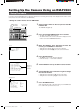
● Machine ID
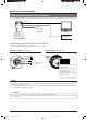
When using a multi-drop system with a remote control unit
such as a RM-P2580, the machine IDs need to be set for
each camera.
Machine IDs are used to identify each of the multiple cam-
eras connected to the RM-P2580. Set the machine IDs ac-
cording to the corresponding VIDEO INPUT terminal num-
bers on the RM-P2580.
(Example)
The machine ID of the camera con-
nected to VIDEO INPUT 1 should be
set to “0” “1” as shown on the right.
Figure of 1
Figure of 10
0
9
8
7
6
5
4
3
2
1
0
9
8
7
6
5
4
3
2
1
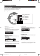
䡵 Setting switches
<Camera ID check procedure>
1.
Set the picture being monitored to that of the camera to
be checked.
2.
Turn the AC 24V power source of the camera OFF and
then ON again.
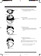
3.
The camera now performs the initialization operation and
the following display appears:
0
9
8
7
6
5
4
3
2
1
0
9
8
7
6
5
4
3
2
1
Figure of 10 Figure of 1
“0” “1”
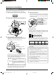
4.
Ensure that “DUPLEX” and “ID-
□□
” are displayed and
that the ID number is identical to the VIDEO INPUT ter-
minal number on the RM-P2580.
5.
If the ID number is incorrect, reset it accordingly.
PROCESSIN TIIAL
UPLEX I D - 10PROT OCLD
I--TI TL:--
I--PNA:--
“DUPLEX” should be displayed. “ID-
□□
” is displayed.
Ensure that the number
□□
is correct.
In a system using an RM-P2580, multiple cameras are connected
by a single set of control cables. An error in the switch setting of
even a single camera will make the entire system inoperable.
MEMO
TK-C676-C655 in_LWT0200-001A-H 04.6.22, 9:29 AM15