OUTDOOR PTZ IP DOME CAMERA VN-V686WPU INSTRUCTIONS (A) Thank you for purchasing this product. Before beginning to operate this unit, please read the instruction manual carefully in order to make sure that the best possible performance is obtained. For Customer Use: Enter below the Serial No. which is located on the body. Retain this information for future reference. Model No. Serial No.
Getting Started Safety Precautions Information for Users on Disposal of Old Equipment [European Union] This symbol indicates that the electrical and electronic equipment should not be disposed as general household waste at its end-of-life. Instead, the product should be handed over to the applicable collection point for the recycling of electrical and electronic equipment for proper treatment, recovery and recycling in accordance with your national legislation.
Due to design modifications, data given in this instruction book are subject to possible change without prior notice. INFORMATION (FOR CANADA) RENSEIGNEMENT (POUR CANADA) This Class A digital apparatus complies with Canadian ICES-003. Cet appareil num rique de la Class A est WARNING (FOR EUROPE): This is a Class A product. In a domestic environment this product may cause radio interference in which case the user may be required to take adequate measures.
Getting Started These are general IMPORTANT SAFEGUARDS and certain items may not apply to all appliances. IMPORTANT SAFEGUARDS 1. 2. 3. 4. Read all of these instructions. Save these instructions for later use. All warnings on the product and in the operating instructions should be adhered to. Unplug this appliance system from the wall outlet before cleaning. Do not use liquid cleaners or aerosol cleaners. Use a damp cloth for cleaning. 5.
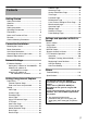
Contents Getting Started Safety Precautions ........................................ 2 Contents........................................................ 5 Features ........................................................ 6 Safety precautions......................................... 7 Operating Environment ................................. 8 Precautions ................................................... 8 Name and Function of Parts ....................... 12 Features ........................................
Getting Started Features Privacy Mask function This function allows you to Blankout areas that you do not wish to display in the location to be recorded. Waterproof and weather-resistant chassis The anti-dust and drip-proof structure will shield the unit from rain, thus enabling it to be installed outdoors directly. (IP66 specifications) Automatic Tracking function This product is equipped with a function that easily tracks moving objects when home position is displayed.
● Before starting an important recording, be sure to perform a test recording in order to confirm that a normal recording is possible. ● We do not accept liability for the loss of a recording in the case of it becoming impossible to record due to a problem in the video camera, VTR, hard disk recorder or video tape. ● The Automatic Tracking function, Intelligent Tracking function and Motion Detection function are simple functions and cannot be used as a substitute for a security alarm.
Getting Started Operating Environment Precautions Recommended Computer Specifications Maintenance and operating environment OS 䢇 This product is specially designed to be mounted on walls. Be sure to place the camera head horizontally. The product will not work properly if it is tilted. 䢇 Do not place this product in the following environments. It might result in malfunctions or failure. ● Hot or cold locations beyond the surrounding temperature range of -40 I to 50 I.
Others 䢇 Do not subject the lens to strong light source such as sun rays. This may cause the equipment to malfunction. 䢇 This camera comes with a built-in AGC circuit. The sensitivity increases automatically at a dark place and the screen may appear grainy. This is not a malfunction. 䢇 While AGC is activated, if a transceiver which causes strong electromagnetic wave is used near the camera, the picture may suffer from beat. Please use the camera more than three meters away from such transceivers.
Getting Started Precautions (continued) Transporting the unit 䢇 Remove the connecting cables when transporting the unit. 䢇 When transporting the unit, turn off the power of the system. 䢇 Pack the unit with cushioning material so as to avoid shock when transporting. 䢇 Handle the unit with care and do not subject it to vibration or shock. Transportation 䢇 Do not throw away the original box of the unit. Keep it and use it for transporting the unit in future.
䡵 Consumable parts 䡵 Zoom Operation The following are consumable parts. They must be replaced once they reach their lifetime. The lifetime is only an estimation and differs according to the usage environment and conditions. Replacement of consumable parts is chargeable within the guarantee period. ● Zoom lens assembly Zoom operation ...... Approx. 2 million operations Focus operation...... Approx. 4 million operations ● Slip ring.......... Approx. 5 million operations ● Cooling fan............... Approx.
Getting Started Name and Function of Parts Camera 䡵 Front side A B C D E A H F G A Camera securing hole (4 locations) F LAN Cable This hole is used for mounting the camera on the wall. This connects the unit to the network. (A Page 22) B Cable connecting hole, cap Remove the cap and pull out the cables from this hole for connection. (A Page 17) C Fall Prevention Wire Connects the camera to the wall. Secure the camera tightly to the anchor bolts used to mount the fall prevention wire on the wall.
䡵 Inner structure of camera L K I J I Heater ON/OFF Switch This is the automatic control ON/OFF switch of the built-in heater. The built-in heater prevents the dome cover from fogging and snow or frost from attaching to the dome cover. When installing the heater at an unrequired location, turn off the switch of the heater. It is usually set to ON. (A Page 17) J Lens Lens cannot be replaced. K Front Mask L [MAC address] indication The MAC address is a unique physical address of the product.
Getting Started Features Surveillance via Dual Stream Surveillance Using Built-in Viewer VN-V686WPU comes with a Built-in ActiveX JPEG Viewer and MPEG4 Viewer. JPEG images and MPEG4 images of VNV686WPU can be monitored using the computer by installing this Built-in Viewer on the computer. JPEG images that are currently displayed can also be captured in the computer’s hard disk.
Camera Mounting Procedures Alarm VN-V686WPU comes with a motion detection feature and dual alarm input. By motion detection or alarm input, actions such as mail delivery, message transmission via TCP/ UDP, alarm output, turning to preset position, changing B&W mode can be triggered. These actions can also be triggered by combination of two alarm inputs. Installing an FTP server enables uploading of JPEG images before and after the alarm input time (pre-/post-recording) to the server.
Connection/Installation Mounting the Camera 4 Pull the cables from the hole in the wall Pull the power cable, LAN cable and alarm signal cable from the wall. Setting Up the Wall LAN Cable Be sure to put on protective glasses to protect your eyes from falling objects when mounting the camera. Power cable 1 Make holes in the wall Make holes (R 45 mm) for the connecting cables to pass through. Alarm signal cable Note: ● Check the strength of the wall. A less firm wall may cause the unit to fall.
2 Remove the cushioning material, lens cap and tape used during transporting When installing the heater at an unrequired location, turn off the switch of the heater. Tape Cushioning material Heater power switch Note: ● Check that there is no dirt or dust inside the dome cover before mounting. ● When installing on a rainy day, ensure that raindrops do not enter the interior. ● When mounting the dome cover, temporarily secure the 4 screws and then tighten. ● As a guide, tighten the screws to 0.
Connection/Installation Mounting the Camera (continued) Mounting the Camera 1 Mounting the fall prevention wire ● Mount the fall prevention wire of the camera to the fall prevention wire anchor bolt that was installed earlier. ● Secure the fall prevention wire tightly with a nut and washer. Cable Connection 1 LAN Cable Connection (A Page 22) A Use the provided RJ-45 conversion connector and connect the LAN cable.
3 Connecting the alarm cable (A Page 22) Connect the alarm cable and wind the waterproof tape (adhesive). After connecting, push the cable into the arm of the camera. 4 Mount the cap 5 Seal the cable connection hole and around the mounting surface of the camera with waterproof seal (GE silicon). Arm 4 Cap 5 Waterproof treatment Wind the waterproof tape (adhesive) Note: ● For cables that are not used, be sure to wrap the ends individually with insulating tape.
Connection/Installation Power Connection Warning Note: ● Be sure to use an AC 24 V supply that is isolated from the primary power supply circuit. Using a variable voltage power supply will cause the camera and system to malfunction or breakdown. ● The unit is to be powered by an AC 24 V power supply. The AC 24 V power supply should conform to the following: Class 2 only (For USA), Isolated power supply only (For Europe and others). Connecting the power cable Connects the camera to AC24V power.
Note: ● If thin cables are used, the resistance of the cables will be high and a significant voltage drop will occur when the camera is at its maximum power consumption (when pan, tilt and zoom operates at the same time). Either use a thick cable with low resistance or place the power supply near to the camera and shorten the length of the cable to restrict the voltage drop at the rated current of camera to below 10 %.
Connection/Installation LAN Cable Connection Connecting the alarm signal cable Connect the camera to a hub or computer using a LAN cable. Cable to use ● Shield (STP) cable ● Make use of a Category 5 (or higher) cable when 100BASE-TX is used. Connect the alarm signal cable to external devices, such as a sensor or buzzer. Cable to use ● Length of 50 m or shorter ● UL1007, UL1015 or equivalent products ● AWG#22 to AWG#18 or equivalent products 䢇 When connecting to a hub Make use of a straight cable.
Alarm input signal Connects to sensors such as infrared sensors, door sensors, metal sensors and manual switches. ● To prevent noise from entering the internal circuit, supply non-voltage contact signal to the alarm input signal. ● Do not supply voltage. ● When the contact is short (MAKE) or open (BREAK) on the menu, you can set it to Alarm. ● Supply such that the alarm signal continues for at least more than 500 ms. The alarm signal may not be recognized if it is less than 500 ms.
Connection/Installation Network Requirements ● Ensure that there is sufficient network bandwidth for the data volume to be sent out by VNV686WPU. Do not send multicast stream that exceeds the bandwidth. If the entire bandwidth is used by the multicast stream, control of this camera via the network may fail. ● Data volume to be sent by VN-V686WPU varies with the settings and number of distributions. ● The maximum bit rate for transmission is about 20 Mbps.
When only MPEG4 images are distributed, the maximum number of distributions is determined by the preset bit rate. When a distribution request that exceeds the maximum number of distributions is received, this request is denied. When distributing only MPEG4 data Maximum number of distributions Total maximum bit rate 0.
Network Settings IP Address Settings 䡵 (B) Assigning a static IP address 䢇 System configuration required for setting IP address Setting the IP address for VN-V686WPU There are two methods to set the IP address for VN-V686WPU as follows. (A) Assigning an IP address to VN-V686WPU from the DHCP server (B) Assigning a static IP address to VNV686WPU 䡵 (A) Assigning an IP address from the DHCP server ● VN-V686WPU is set to ADHCP EnableB (the DHCP client function is ON) by default.
䢇 IP address setting at the computer Set the computer to an IP address that enables communication with VN-V686WPU. 1 Click [Start] ● Select in the sequence of [Control Panel]-[Network Connection]-[Local Area]. 2 The computer on which Internet Explorer is launched automatically selects the connected network ● Right-click and select [Properties]. ● Check to ensure that the [Client for Microsoft Networks] and [Internet Protocol(TCP/IP)] check boxes are selected.
Network Settings IP Address Settings (continued) 䢇 Changing the IP address using the Internet Explorer 1 Launch the Internet Explorer on the computer 2 When proxy settings are enabled in the Internet Explorer, follow the steps below to disable the proxy of the Internet Explorer ● Select in the order of [Tool]-[Internet Options]-[Connections]-[LAN Setting], followed by deselecting the check for [Use a proxy server for your LAN] under [Proxy Server] of the [Local Area Network (LAN) Settings] window.
4 Launch the Internet Explorer A Enter the following IP address into the address field. http://192.168.0.2 B Click [Go]. Memo: ● If the proxy server settings for access to the Internet via the Internet Explorer is enabled, you may not be able to specify the IP address directly. In this case, change the proxy settings of the Internet Explorer. ● After the [Security Settings] screen appears, press the [OK] button to proceed.
Network Settings IP Address Settings (continued) 䢇 Changing the IP address using the Internet Explorer (continued) 6 The top page of VN-V686WPU appears Click on [Network], followed by [Basic] on the next submenu. 7 The [Basic] page with the IP address settings appears A Set the [IP Setting] item to [DHCP Disable]. B Enter the values you wish to specify in the [IP Address], [Subnet Mask] and [Default Gateway] fields. C Click [OK]. A confirmation screen appears. Press the [OK] button.
When the IP address of VN-V686WPU is known When the IP address of VN-V686WPU is known, it can be changed by accessing the built-in web page of VN-V686WPU via the Internet Explorer on the computer. Refer to [Setting Using Internet Explorer] (A Page 32). When the IP address of VN-V686WPU is unknown IP address settings cannot be changed by accessing via a computer when the IP address of VN-V686WPU is unknown. Use [Search tool] in the provided CD-ROM to find the IP address.
Setting Using Internet Explorer Preparation Internet Explorer Setup 1 Launch the Internet Explorer on the computer 2 When proxy settings are enabled in the Internet Explorer, follow the steps below to disable the proxy of the Internet Explorer ● Select in the order of [Tool]-[Internet Options]-[Connections]-[LAN Setting], followed by deselecting the check for [Use a proxy server for your LAN] in [Proxy Server] of the [Local Area Network (LAN) Settings] window.
3 If ActiveX controls and plug-ins of the Internet Explorer is disabled, follow the steps below to enable it ● Click [Trusted sites] under [Tool]-[Internet Options]-[Security]. Click on the [Sites…] button directly below, followed by deselecting the check [in the displayed window]. Add the following web site to the zone. http://192.168.0.2 ● Click [Trusted sites] under [Tool]-[Internet Options]-[Security]. Select the [Custom Level] button and open the [Security Settings] window.
Setting Using Internet Explorer Preparation (continued) Utility [Maintenance] [Miscellaneous] Status [Operation] [Settings] [Position List] [Patrol Settings 0] [Patrol Settings 1] [Patrol Settings 2] Enter user name and password User name and password entry will be required at the beginning. There are three access authorization levels to VN-V686WPU. The factory settings are as follows.
● user Image [View] Utility [Miscellaneous] Memo: ● Security Information window may appear before the top page is displayed. Press the [OK] button to proceed. If you do not want this warning screen to be displayed, change the Internet Explorer settings as follows. ● Open [Tool]-[Internet Options][Security] and select the [Trusted sites] icon. ● Next, press the [Custom Level] button, followed by selecting AEnableB for [Miscellaneous]-[Display mixed content].
Setting Using Internet Explorer Setting View Page This top page is displayed upon access using any of the user names AadminB, AoperatorB or AuserB. The current image is displayed as a still image. Links to each page are found at the left end. The links displayed vary according to the user name. For example, in the case of AadminB or AoperatorB, three links, namely [View], [Camera] and [Encoding] are displayed upon clicking [Image]. In the case of AuserB, only [View] is displayed.
A Reload Still Image Press this button to refresh the displayed still image. Clicking [View] or re-entering the Internet Explorer address will only display the page that is temporarily stored in the Internet Explorer, and still images may not be refreshed. To refresh still images using the above operations, change the Internet Explorer settings as follows. ● Open [Tool]-[Internet Options], click the [Settings] button under Temporary Internet Files, and select AEvery visit to the pageB.
Setting Using Internet Explorer Setting (continued) Camera Page This page is for setting the camera’s parameters. This page can be used during access using AadminB or AoperatorB. ● Press the [OK] button to enable the new settings. ● If the [OK] button is pressed upon entering an invalid value, a warning message will appear and the entry will be denied. Press the [Cancel] button to restore the invalid entry to the current value.
C Black Level For adjusting the black level. Lowering the value darkens the video image. Increasing the value brightens the image. [Setting range : 0 to 2] Memo: ● If the black level is set to A0B, this may be too low depending on the connected device, or dark area will become complete black. ● When using MPEG4 images, set to either A1B or A2B. D Gamma To alter the appearance of dark areas in a video image, adjust the gamma curve. 0 : Gamma correction suitable for CRT is performed.
Setting Using Internet Explorer Setting (continued) Camera Page (continued) A B C D E F G H I J K L M H Stabilizer This function prevents image shaking caused by vibration. Set this function to AOnB to control image shaking. Off : Disabled. On : Enabled. Memo: ● When the function is set to AOnB, the screen is enlarged to approximately 1.3 times. ● Adjustment is disabled in the electronic zoom area. ● Adjustment is disabled for about 1 minute after power ON and during Pan/Tilt/ Zoom operation.
I Stabilizer Level J Noise Reduction This item allows you to set the adjustment level of the [Stabilizer] item H in 3 steps. The adjustment volume is larger if the value is set to AHighB rather than AMidB. When it is set to ALowB, the adjustment volume is lesser than compared to when it is set to AMidB. [Setting values : Low,Mid,High] When AOnB is set, image noise on the screen will be reduced. Memo: ● This item is only enabled when [AGC] item K is set to AHighB or ASuperB.
Setting Using Internet Explorer Setting (continued) Camera Page (continued) A B C D E F G H I J K L M 42
L Shutter Speed This item sets the speed of the electronic shutter. When [Sense Up] item K is set to Ax2B or above, available setting value is A1/60B or A1/100B only. [Setting values : 1/60,1/100,1/250,1/500,1/1000,1/2000,1/4000,1/10000] Memo: ● Flickering of fluorescent lightings can be reduced when the shutter speed is set to A1/100B or A1/60B respectively in regions of commercial power frequency 50 Hz and 60 Hz.
Setting Using Internet Explorer Setting (continued) Encoding Page This page is for setting JPEG and MPEG4 encoding parameters. This page can be used during access using AadminB or AoperatorB. ● Press the [OK] button to enable the new settings. ● If the [OK] button is pressed upon entering an invalid value, a warning message will appear and the entry will be denied. Press the [Cancel] button to restore the invalid entry to the current value.
JPEG B Quality/Size For specifying the rate control mode and target file size for JPEG. When AVFS1B to AVFS7B is selected, the quantization table during JPEG encoding will be maintained and the file size will increase/decrease according to the input signals. Stipulated values will be displayed in the Size field. When recording JPEG data to a recorder with a limited storage capacity, note that the maximum recording time may vary as the file size fluctuates under this setting.
Setting Using Internet Explorer Setting (continued) Alarm Page This page is for setting actions when there is an alarm. Up to 5 actions (No. 01 to No. 05) may be set. This page can be used during access using AadminB or AoperatorB. ● Press the [OK] button to enable the new settings. Only items that are valid under the selected action will be saved. When Disable is selected for the action, all settings will be restored to their default values.
A Action For specifying the type of action. Disable : Does not trigger any action. Mail : Sends out e-mail. Specify the recipient’s mail address. The title of the mail will appear as [Alarm from VN-V686] and the sender as [Camera ID]. Enter the message to send in [Mail Text]. Input up to 127 alphanumeric characters. To attach the latest image to the mail, set [Attach Image] to AOnB. PrePostRecording + FTP : Sends out pre-/post-recorded JPEG files via FTP.
Setting Using Internet Explorer Setting (continued) Alarm Page (continued) A B C D E F G H I J B 1st Trigger This item specifies the first trigger to the operation set in [Action] A. [Setting values: Input 1 Make, Input 2 Make, Input 1 Break, Input 2 Break, Motion Detection, Fan Stop, Position, BlackWhite → Color, Color → BlackWhite] Memo: ● When the second trigger is turned off, the action will be invoked only by the first trigger.
C Max. Interval Enabled when both the first and second triggers are specified. Specify the maximum interval between the first and second triggers. An action will be invoked only if the interval between the first and second triggers is within the maximum interval. [Setting range : 1sec to 3600sec] D 2nd Trigger This item specifies the second trigger to the operation set in [Action] A.
Setting Using Internet Explorer Setting (continued) Alarm Environment Page This page is for setting alarm-related environments. This page can be used during access using AadminB or AoperatorB. ● Press the [OK] button to enable the new settings. ● If the [OK] button is pressed upon entering an invalid value, a warning message will appear and the entry will be denied. Press the [Cancel] button to restore the invalid entry to the current value.
A Mail For setting the mail environment when AMailB is specified as an [Action]A on the Alarm page. [SMTP] and [POP] can be used. Configure only the [SMTP] settings under usual circumstances. Enter the camera’s mail address as the [Send Mail Address]. Configure the [POP] settings as well if [POP before SMTP] is set to AOffB. In addition, if AFQDNB is set for [SMTP Server], configure also the [DNS Server] settings on the Basic page.
Setting Using Internet Explorer Setting (continued) Alarm Environment Page (continued) B C 52
B FTP (continued) Time Filter : For specifying the periodic FTP transfer action with respect to each day of the week and setting the corresponding time of the day. Applicable day of week : Sunday, Monday, Tuesday, Wednesday, Thursday, Friday, Saturday Alarm action : Mask span Unmask span Mask All Unmask All Applicable time period : For specifying the Start and End time in hours and minutes.
Setting Using Internet Explorer Setting (continued) PTZ Page A B C D E F A Auto Return If the camera is not operated over the duration that was set in AReturn TimeB, it will automatically return to the state that was set in AModeB. Mode This item sets the operation after Auto Return. none : Auto Return is disabled. Home : Returns to the home position. Auto Pan : Returns to the Auto Pan operation. Auto Patrol : Returns to the Auto Patrol operation. Auto Trace : Returns to the Auto Trace operation.
B Auto Tracking/ Intelligent Tracking This item sets the Auto Tracking and Intelligent Tracking settings. Auto Tracking: Moves to the home position when Auto Return starts. This function automatically tracks and shoots moving objects when motion is detected from the image at the home position. The zoom ratio is fixed at 1x. Intelligent Tracking: There are two modes for Intelligent Tracking; the Auto mode which starts from Auto Return and the Manual mode which specifies the target on the viewer.
Setting Using Internet Explorer Setting (continued) PTZ Page (continued) BAuto Tracking/ Intelligent Tracking (continued) Note: ● The Auto Tracking function of this camera detects changes in brightness. As such, depending on changes in the illumination, it may or may not detect movement of objects having the same color as the background color. It may be difficult to detect objects with very slow movement.
D Limit EZoom Limit When the zoom lens is operated to TELE side, optical zoom works and electronic zoom works after optical zoom becomes full. This item sets the maximum value of the electronic zoom function. [Setting range : Off, 1, 2, 4, 8, 16, 32] Memo: ● As electronic zoom processes the images digitally, image quality will deteriorate somewhat. ● Increasing the electronic zoom ratio will shift the center of the screen toward the top left.
Setting Using Internet Explorer Setting (continued) PTZ Page (continued) CLimit (continued) Tilt Limit This item sets the movable range of the tilt (vertical) operation during manual operation. When this item is set to 10, the movable range of the tilt operation is from 10 to 90 degrees. It cannot operate between -5 and 9 degrees.
F Auto Flip Set this item when shooting objects that pass right under the camera. Otherwise, following operations are necessary to shoot objects that pass right under the camera. ATurn the camera to face down BRotate the camera 180 ⬚ horizontally CTurn the camera to face up You can use the [Auto Flip] function to perform the above operations automatically. Off : Auto Flip function does not activate.
Setting Using Internet Explorer Setting (continued) Auto Patrol Page This function sets the Auto Patrol operation which patrols multiple positions at specified time intervals. You can set the order in which to view the determined positions.
There are three screens in Auto Patrol. A B C D A No This is sequence number of the mode of Auto Patrol. B Title This displays the title of the position. C Position This sets the position number to be moved in sequence. [Setting values : 0 to 99] D Time This sets the duration of staying at the position.
Setting Using Internet Explorer Setting (continued) Privacy Mask Page Privacy Mask is a feature that enables masking of a portion of the image. You can set 8 rectangular privacy masks for VN-V686WPU. This page can be used during access using AadminB or AoperatorB. ● Press the [OK] button to enable the new settings.
A Privacy Mask For specifying whether to activate the Privacy Mask feature. When this is set to AOnB, the privacy mask specified using the following items will appear on the screen. Memo: ● When setting privacy mask, zoom will be at the Wide edge and [Digital Flip] is set to AOffB. B Adjustment This item adjusts the mask. Click this item to open the [Adjustment] screen. To change the setting, first, enter [Operator Password] in the [Password] screen.
Setting Using Internet Explorer Setting (continued) Motion Detection Page This page is for setting motion detection. ● The area valid for motion detection is displayed in blue. ● When motion is detected, the image screen edge is displayed in red. ● Information of the configured mask is also applicable for detecting the tracking target of Intelligent Tracking, which starts from Auto Return.
A Display Screen The screen is divided into blocks of 12 (horizontal) x 8 (vertical). Use this to set whether to mask each block. All blocks are masked in the default setting. The block turns blue when it is clicked, indicating that it is unmasked. Click again to return to the masked state. Press the [OK] button to enable this setting. Use the [Mask All] button to mask all blocks. Use the [Clear Mask] button to unmask all blocks. B Detection For setting the On/Off of [Detection].
Setting Using Internet Explorer Setting (continued) Basic Page This page is for performing basic setting related to the network. This page can be used during access using AadminB. ● Press the [OK] button to enable the new settings. ● If the [OK] button is pressed upon entering an invalid value, a warning message will appear and the entry will be denied. Press the [Cancel] button to restore the invalid entry to the current value.
A IP Setting For setting the DHCP client function. Connect VN-V686WPU to a network environment with a DHCP server when DHCP is to be enabled. If the DHCP server does not exist when DHCP is set to AEnableB, VNV686WPU will start running with the 192.168.0.2 IP address and 255.255.255.0 subnet mask in about 2 minutes after startup. Refer to [IP Address Settings] (A Page 26) for the IP address. B IP Address For setting the IP address of VN-V686WPU. C Subnet Mask For setting the subnet mask of VN-V686WPU.
Setting Using Internet Explorer Setting (continued) Details Page This page is for performing detailed network setting. This page can be used during access using AadminB. ● Press the [OK] button to enable the new settings. ● If the [OK] button is pressed upon entering an invalid value, a warning message will appear and the entry will be denied. Press the [Cancel] button to restore the invalid entry to the current value.
Protocol Page This page is for changing the HTTP server port number, VSIP server status, and VSIP server port number. This page can be used during access using AadminB. ● Press the [OK] button to enable the new settings. ● After changing, you will need to re-establish the connection if you are using the Internet Explorer. A B C A HTTP Server Port You can change the port number for Built-in web server of VN-V686WPU. (165535) The default port number setting is A80B.
Setting Using Internet Explorer Setting (continued) Streaming Page This page is for setting manual multicast transmission. This page can be used during access using AadminB or AoperatorB. ● Press the [OK] button to enable the new settings. ● If the [OK] button is pressed upon entering an invalid value, a warning message will appear and the entry will be denied. Press the [Cancel] button to restore the invalid entry to the current value.
JPEG A Control For starting or stopping streaming of JPEG images. Parameters that are set on the [Streaming] page will be saved when transmission is started upon pressing the [Start] button. B Destination For specifying the destination address of JPEG streaming. Specify the multicast address. When other devices that make use of multicast transmission exist, ensure that each of them is set to a different multicast address.
Setting Using Internet Explorer Setting (continued) Access Restrictions Page This page is for setting client restrictions. This page can be used during access using AadminB. ● Press the [OK] button to enable the new settings. ● If the [OK] button is pressed upon entering an invalid value, a warning message will appear and the entry will be denied. Press the [Cancel] button to restore the invalid entry to the current value. ● This feature is targeted at JPEG/MPEG4 acquisition.
Destination Address A Access Restrictions B IP Address Restrictions may be imposed on clients accessing VN-V686WPU using the IP address. When AdenyB is selected, acquisition of JPEG/MPEG4 via the IP address specified for the [IP Address] item B will be denied. Restrictions are not imposed on access to the Web Settings page. When AallowB is selected, acquisition of JPEG/MPEG4 via the IP address specified for the [IP Address] item B will be permitted.
Setting Using Internet Explorer Setting (continued) Time Page This page is for setting time. This page can be used during access using AadminB. ● Press the [OK] button to enable the new settings. ● If the [OK] button is pressed upon entering an invalid value, a warning message will appear and the entry will be denied. Press the [Cancel] button to restore the invalid entry to the current value. A B C D E F A SNTP For setting the SNTP client feature.
Password Page This page is for setting the password. This page can be used during access using AadminB. ● Press the [OK] button to enable the new settings. A B C A Username Select a user name. B New Password Enter a new password. Passwords shall be at least 4 characters and not longer than 16 characters. VN-V686WPU is case sensitive. C New Password Enter again to confirm the new password. Again Note: ● Be sure to handle the password carefully in case you forget it.
Setting Using Internet Explorer Setting (continued) Maintenance Page This page is for maintenance purposes. This page can be used during access using AadminB.
A Restart Reboots the camera. (It takes a few minutes for the camera to reboot.) B All Settings [Initialize] Restores all settings to their default values and reboots the unit. (It takes about one minute for the camera to initialize and reboot.) Passwords will also be initialized. The built-in clock of VN-V686WPU will not be affected. JPEG/MPEG4 transmission and all other services that are running will be discontinued. C Update Upgrades the firmware version of VN-V686WPU and reboots the unit.
Setting Using Internet Explorer Setting (continued) 䡵 Encoding Page Item List of Factory Settings of Each Page 䡵 Camera Page Factory Settings JPEG Frame Size VGA MPEG4 Frame Size VGA JPEG Quality VFS4 MPEG4 Bitrate 2000 kbps CBR Factory Settings MPEG4 Bitrate Control Camera ID VN-V686 MPEG4 FPS 15 fps Monitor Type Custom MPEG4 I Frame Interval 30 Black Level 1 MPEG4 Priority FPS Gamma 1 Active Gamma Level 0 Enhance Frequency High Enhance Level 0 Action Disable Color Leve
䡵 Alarm Environment Page Item 䡵 PTZ Page Factory Settings Item Factory Settings SMTP Server 0.0.0.0 Mode Port Number 25 Return Time 1 minute Send Mail Address ^ Off POP before SMTP Off Auto Tracking/Intelligent Tracking Restart Time POP Server 0.0.0.0 5 none Port Number 110 Auto Tracking/Intelligent Tracking Auto Tracking Level Username ^ Tracking Zoom On Password ^ Tracking Zoom Limit 10 Times FTP Server 0.0.0.
Setting Using Internet Explorer Setting (continued) 䡵 Details Page Item List of Factory Settings of Each Page (Cont’d) 䡵 Auto Patrol Page Factory Settings JPEG TOS 0 MPEG4 TOS 0 TTL (Unicast) 64 TTL (Multicast) 32 Factory Settings MTU 1500 Position (Preset position number) Negotiation Auto Time 10 Item Item 䡵 Privacy Mask Page Item 䡵 Protocol Page Factory Settings HTTP Server Port 80 Factory Settings VSIP Protocol Off Privacy Mask Off VSIP Server Port 5510 Mask 0 to 7 Off
䡵 Access Restrictions Page Item Factory Settings Access Restrictions deny IP Address — 䡵 Time Page Item Factory Settings SNTP Off NTP Server 192.168.0.
Setting Using Internet Explorer Setting (continued) Miscellaneous page This page is for acquiring information. This page can be used during access using AadminB, AoperatorB and AuserB. A A Open Source Software 82 Press the [Show] button to display information of the software used by VNV686WPU.
Operation Page Displays the operating status of VN-V686WPU. This page can be used during access using AadminB or AoperatorB. A B C A Total Sending Bitrate Displays the total TCP/UDP bit rate sent by VN-V686WPU as well as the individual bit rates. B Destination Displays the destination that VN-V686WPU is sending data to. C System Log Displays the following information.
Setting Using Internet Explorer Setting (continued) Settings Page This page displays the version information and settings of VN-V686WPU. This page can be used during access using AadminB or AoperatorB.
Setting Using Internet Explorer Setting (continued) Settings Page (continued) 86
Position List Page This page displays information on preset positions. This page can be used during access using AadminB or AoperatorB.
Setting Using Internet Explorer Setting (continued) Position List Page (continued) 88
Patrol Settings Page This page displays the information and settings of Auto Patrol. This page can be used during access using AadminB or AoperatorB.
Setting Using Internet Explorer Setting (continued) Patrol Settings Page (continued) 90
Settings and operation of Built-in Viewer Built-in Viewer This product comes with a JPEG Viewer and an MPEG4 Viewer. Each of these viewers functions separately. 䡵 Using the JPEG Viewer enables display of a series of still images as well as saving of still images. 䡵 Using the MPEG4 Viewer enables display of MPEG4-encoded motion images.
Settings and operation of Built-in Viewer Preparation Internet Explorer Setup 1 Launch the Internet Explorer on the computer 2 When proxy settings are enabled in the Internet Explorer, follow the steps below to disable the proxy of the Internet Explorer ● Select in the order of [Tool]-[Internet Options]-[Connections]-[LAN Setting], followed by deselecting the check for AUse a proxy server for your LANB in [Proxy Server] of the [Local Area Network (LAN) Settings] window.
3 If ActiveX controls and plug-ins of the Internet Explorer is disabled, follow the steps below to enable it ● Click [Trusted sites] under [Tool]-[Internet Options]-[Security]. Upon doing so, the [Sites…] button directly below becomes active. Click this button and deselect the check [in the displayed window]. Next, add the IP address of VN-V686WPU. If the setting is factory default, add the following web site to the zone. http://192.168.0.2 ● Click [Trusted sites] under [Tool]-[Internet Options]-[Security].
Settings and operation of Built-in Viewer Preparation (continued) Installing Built-in Viewer 1 Enter the URL of Built-in Viewer in the address field of Internet Explorer For example, if the IP address of VN-V686WPU is 192.168.0.2, enter as follows: 䡵JPEG Viewer http://192.168.0.2/cgi-bin/v686viewing.cgi?v686monitor_j.html 䡵MPEG4 Viewer http://192.168.0.2/cgi-bin/v686viewing.cgi?v686monitor_m.html Enter the URL in Built-in Viewer of this camera. (Refer to the above for the default URL setting.
JPEG Viewer Screen Configuration of JPEG Viewer ● When the JPEG Viewer is first installed, it is set to play back at 15 fps by default. A B C D E A DisplaySize Switches the display size. (VGA or QVGA) Note: ● When the VGA JPEG is reduced to QVGA and when QVGA JPEG is enlarged to VGA, the load on the computer will increase. B Capture Captures the currently displayed image on the computer. Images captured will be stored as a JPEG file in the folder created under [My Document] of the computer.
Settings and operation of Built-in Viewer JPEG Viewer (continued) Exiting the JPEG Viewer (continued) D PTZ Open the [PTZ Controller] screen. Manual operations are available. Configure settings of preset position registration and Auto Pan/Auto Trace in the [PTZ Controller] screen. (A Page 106) Note: ● When the PTZ Controller screen is first opened in the computer, ActiveX will be installed. E Setup Displays Built-in Viewer settings window.
A On Screen Display Settings For setting display items on the viewer screen. For the JPEG Viewer, characters are displayed as overlay on the video image. Camera ID Select AOnB to display [Camera ID]. (Up to 16 alphanumeric characters will be displayed.) [Camera ID] can be specified on the Camera page of VN-V686WPU. (A Page 38) PositionTitle Select AOnB to display the title of the position that is being displayed. Motion Detection Selecting AOnB displays the area in which motion is detected in red.
Settings and operation of Built-in Viewer JPEG Viewer (continued) JPEG Viewer Configuration (continued) BStream Settings (continued) Multicast IP Address You can change the multicast IP address. The default IP address setting is A225.0.1.1B. Multicast Port You can change the multicast port number. The default port number setting is A49152B. Memo: ● This is enabled when AStartB is selected for the [JPEG Control] item on the [Streaming] page.
Exiting the JPEG Viewer To exit, press the [close] [X] button at the top right of the window. Click [X]. ● During the next startup of Built-in Viewer, launch the Internet Explorer and enter the URL of Built-in Viewer in the address field. For example, if the IP address of VN-V686WPU is 192.168.0.2, enter as follows: http://192.168.0.2/cgi-bin/v686viewing.cgi?v686monitor_j.html ● After the [Security Settings] screen appears, press the [OK] button to proceed.
Settings and operation of Built-in Viewer MPEG4 Viewer Screen Configuration of MPEG4 Viewer A B C D A DisplaySize Switches the display size. (VGA or QVGA) Note: ● When the VGA JPEG is reduced to QVGA and when QVGA JPEG is enlarged to VGA, the load on the computer will increase. B Pause Pauses/Resumes playback of motion images. C PTZ Open the [PTZ Controller] screen. Manual operations are available.
D Setup Displays Built-in Viewer settings window. This setting screen is used to set Built-in Viewer as a software on the computer. Note: ● Settings on this setting screen do not affect settings of the VN-V686WPU unit. Memo: ● To use Built-in MPEG4 Viewer of VN-V686WPU, install “ffdshow” that is open source codec. You can download “ffdshow” from the Internet. MPEG4 Viewer Configuration The MPEG4 Viewer’s settings window appears upon clicking the [Setup] button of the viewer.
Settings and operation of Built-in Viewer MPEG4 Viewer (continued) MPEG4 Viewer Configuration (continued) A Title Bar Display Settings For setting display items on the viewer screen. For the MPEG4 Viewer, characters are displayed in the title bar of the window. Camera ID Select AOnB to display [Camera ID]. (Up to 16 alphanumeric characters will be displayed.) [Camera ID] can be specified on the [Camera] page of VN-V686WPU.
B Stream Settings (continued) Multicast Port You can change the multicast port number. The default port number setting is 59152. Memo: ● This is enabled when AStartB is selected for the [JPEG Control] item on the [Streaming] page. ● Specify the same value as the parameter that is set on the [Streaming] page of VN-V686WPU. (A Page 71) C Operator Password Operator password is required to control VN-V686WPU and to get preset position title from VN-V686WPU.
Settings and operation of Built-in Viewer MPEG4 Viewer (continued) Exiting the MPEG4 Viewer To exit, press the [close] [X] button at the top right of the window. Click [X]. ● During the next startup of Built-in Viewer, launch the Internet Explorer and enter the URL of Built-in Viewer in the address field. For example, if the IP address of VN-V686WPU is 192.168.0.2, enter as follows: http://192.168.0.2/cgi-bin/v686viewing.cgi?v686monitor_m.
Shortcut for Built-in Viewer Creating a shortcut for Built-in Viewer on the Desktop screen of the computer saves you the trouble of having to enter the URL in the Internet Explorer. Create the shortcut by following the procedure below. 1 Launch the Internet Explorer 2 Right-click at an arbitrary point on the Internet Explorer screen and select [Create Shortcut] Click the [OK] button on the confirmation screen and a shortcut will be created on the Desktop screen.
Settings and operation of Built-in Viewer PTZ Controller Operation Operation The [PTZ Controller] window appears upon clicking the [PTZ] button of Built-in Viewer. Configure settings for the camera manual operation, preset position registration and Auto Pan/Auto Trace operation in the [PTZ Controller] screen. Note: ● Before using PTZ Controller, enter operator password to setup window of Built-in Viewer. ● When the PTZ Controller screen is first opened in the computer, ActiveX will be installed.
B Auto Function Function For selecting the operation. Click [Start] to start the selected Auto function. Click [Stop] to stop the running Auto function. A list of patrol modes appears when AAuto PatrolB is selected. A list of targets appears when AIntelligent TrackingB is selected. Auto Pan : The configured Auto Pan operation is performed. (A Page 113) Auto Patrol : The configured Auto Patrol operation is executed. Select [Patrol Mode].
Settings and operation of Built-in Viewer PTZ Controller Operation (continued) Operation (continued) D Zoom This item sets the zoom operation of the lens when clicking the button. + : Zoom is set to TELE and the object becomes bigger. : Zoom is set to WIDE and the object becomes smaller.
H B/W Mode This sets the function to switch from Color to B&W mode. Color : Always be in Color mode. Black & White : Always be in B&W mode. Auto Low,Auto Mid,Auto High : This item automatically switches between Color Mode and B&W Mode when the luminance meets defined conditions over 30 seconds. Select the sensitivity from three options.
Settings and operation of Built-in Viewer PTZ Controller Operation (continued) Operation (continued) K White Balance (continued) R Gain Adjusts the R (red) hue during AWC. + : Increases the redness or red level. : Decreases the redness or red level. [Setting values : 0 to 255] Memo: ● Click the button once to change to the next value. To change the value continuously, click repeatedly. The value will not change if the button remains pressed down. B GAIN Adjusts the B (blue) hue during AWC.
Intelligent Tracking (Manual Mode) This function allows you to track and shoot the color information of an object, which was selected by clicking on the viewer screen. A Select [Intelligent Tracking]. B Click [Start] Standby ● The camera will go into Standby mode and AStandbyB will be displayed on the top right of the viewer screen.(JPEG Viewer) ● The camera will go into Standby mode and AStandbyB will be displayed on the title bar.
Settings and operation of Built-in Viewer PTZ Controller Operation (continued) Registering Preset Positions The [PTZ Controller] window appears upon clicking the [PTZ] button. Click the [Position Memory] tab of the [PTZ Controller] screen and register the preset positions in the [Position Memory] screen. Note: ● When [Auto Flip] is set to ADigital FlipB, preset positions cannot be registered when the tilt angle is more than 90 degrees.
A Click the [Position Memory] tab to display the [Position Memory] screen. B Select [Position]. [Setting values : HOME, 0 to 99] C The current title appears. Enter here to register or change the title. (Up to 32 alphanumeric characters can be entered.When Built-in JPEG Viewer is used, up to 16 alphanumeric characters are displayed.) D Operate the camera and adjust the angle and image quality of the position to be registered. Memo: ● For details on the adjustment method, see [Operation] (A Page 106).
Settings and operation of Built-in Viewer PTZ Controller Operation (continued) Auto Pan Setting (continued) A Click the [Auto Pan] tab to display the [Auto Pan] screen. B Select the [Mode] of the Auto Pan operation. Right : This rotates the camera horizontally in the right direction from the [Start Position]. Left : This rotates the camera horizontally in the left direction from the [Start Position].
Auto Trace Setting This item stores and reproduces manual operation. Click the [Auto Trace] tab on the [PTZ Controller] screen and configure settings at the [Auto Trace] setting screen. Note: ● As Auto Trace performs simple saving of manual operation, the position may be shifted during playback. ● ADigital FlipB cannot be used during Auto Trace recording. [Auto Flip] (A Page 59) the [Auto Trace] tab to display the [Auto A Click Trace] screen. [Record Start].
Others Troubleshooting Symptom Causes and Countermeasures Video image does not appear Power does not turn on. ● Is there a problem with the power cable connecting this unit and the power unit? (If the power cable is too long or thin, the cable resistance will be high and the correct voltage may not be supplied.) Reference Page A Page 20 BUse a cable of low resistance and the correct cable length.
Symptom Causes and Countermeasures Reference Page Multicast images cannot be played back ● Start multicast transmission manually from the [Streaming] page of VN-V686WPU. ● In the case of multicast reception at Built-in Viewer, check that the multicast address and port number of Built-in Viewer settings coincide with those on the [Streaming] page of VN-V686WPU. Make use of a network that supports IGMP v2 for multicast transmission. ● Multicast may be blocked by the WindowsXP firewall.
Others Troubleshooting (continued) Symptom Causes and Countermeasures Reference Page A Page 24 TCP images cannot be played back The maximum number of images that can be sent by VN-V686WPU via TCP is 20, and up to 20 Builtin Viewers can be connected to each VN-V686WPU unit. Make use of multicast for monitoring when the number of areas exceeds the above number. VN-V686WPU allows multicast transmission of JPEG and MPEG4 one stream at a time.
Specifications 䡵 Camera Head Image pickup device : 1/4 type, Interline Transfer CCD 768 (H) x 494 (V) Minimum object illumination Color : 1.0 lx (50 % output, AGC Super, WIDE edge, Monitor Type CRT, Black Level 2) 0.5 lx (25 % output, AGC Super, WIDE edge, Monitor Type CRT, Black Level 2) During B&W : 0.08 lx (50 % output, AGC Super, WIDE edge, Monitor Type CRT, Black Level 2) 0.
Others Specifications (continued) 䡵 Accessories :Start-up Guide ...................................... 1 CD-ROM ............................................. 1 Warranty Card (For USA).................... 1 Service Information Card (For USA) ... 1 RJ-45 Conversion Connector..............
VN-V686WPU OUTDOOR PTZ IP DOME CAMERA © 2008 Victor Company of Japan, Limited LST0677-001C