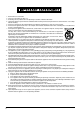
R DIGITAL VIDEO RECORDER VR-510U INSTRUCTIONS DIGITAL VIDEO RECORDER VR-510U POWER TIMER CANCEL REV WARNING SLEEP SELECT MENU REC STOP DISPLAY SEARCH PLAY STILL FWD REC CLOCK RESET/ CLEAR EXECUTE OPE. LOCK ON SKIP/ALARM SEARCH For Customer Use: Enter below the Serial No. which is located on the rear of cabinet. Retain this information for future reference. Model No. VR-510U Serial No.
1. 2. 3. 4. 5. 6. 7. 8. 9. 10. 11. 12. 13. 14. 15. 16. 17. 18. 19. 2 Read all of these instructions. Save these instructions for later use. All warnings on the product and in the operating instructions should be adhered to. Unplug this appliance system from the wall outlet before cleaning. Do not use liquid cleaners or aerosol cleaners. Use a damp cloth for cleaning. Do not use attachments not recommended by the appliance manufacturer as they may cause hazards.
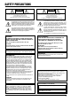
SAFETY PRECAUTIONS CAUTION ATTENTION RISK OF ELECTRIC SHOCK DO NOT OPEN RISQUE D’ELECTROCUTION NE PAS OUVRIR CAUTION: TO REDUCE THE RISK OF ELECTRIC SHOCK, DO NOT REMOVE COVER (OR BACK). NO USER-SERVICEABLE PARTS INSIDE. REFER SERVICING TO QUALIFIED SERVICE PERSONNEL ATTENTION: POUR EVITER TOUT RISQUE D’ELECTROCUTION NE PAS OUVRIR LE BOITER. AUCUNE PIECE INTERIEURE N’EST A REGLER PAR L’UTILISATEUR. SE REFERER A UN AGENT QUALIFIE EN CAS DE PROBLEME.
Thank you for purchasing the JVC VR-510U digital video recorder. CONTENTS 1. INTRODUCTIONS 1-1 Precautions ................................................................. 5 2. CONTROLS, CONNECTIONS AND DISPLAY 2-1 Front panel .................................................................. 6 2-2 Rear panel .................................................................. 7 2-3 Display ........................................................................ 8 3.
1 INTRODUCTION Major features ● Large-capacity hard disk (80 GB) Large-capacity hard disk enables high-quality/high-capacity recording/playback. (Can be increased up to 160 GB) JVC cannot accept liability for loss or damage to recording that result from a malfunction of this unit or the hard drive. ● Simultaneous recording/playback mode You can play or back up programs even during recording. ● Instant picture search You can access images at a specified date/time or alarm point instantly.
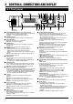
2 CONTROLS, CONNECTIONS AND DISPLAY 2-1 Front panel 2 3 4 5 6 TIMER CANCEL MENU DISPLAY SEARCH PLAY STILL 7 8 9 10 11 12 DIGITAL VIDEO RECORDER VR-510U POWER SELECT REV WARNING 1 REC SLEEP STOP FWD REC CLOCK RESET/ CLEAR EXECUTE OPE. LOCK ON SKIP/ALARM SEARCH 20 * Behind the cover 19 18 1 [LITHIUM BATTERY] battery box for memory backup Install a memory backup battery. When replacing the battery with a new one, be sure to set the date/time again.
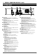
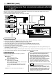
2 CONTROLS, CONNECTIONS AND DISPLAY (contd.) 2-2 Rear panel 26 28 27 21 POWER ON CAMERA IN 1 AUDIO IN I O OFF RS-232C 1 1 2 2 CAM SW ALARM ALARM CLOCK EXT SPARE RESET RESET IN REC IN OUT IN1 HDD CLOCK SPARE SPARE COM RESET OUT FULL OUT COM SIGNAL GND 25 24 & [STOP] button * ( ) q w e AC IN 120 V 50 Hz / 60 Hz AUDIO OUT MONITOR OUT Press this button to stop operation. In the Simultaneous Playback mode, press this button to stop playback and engage the normal recording mode.
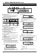
2 CONTROLS, CONNECTIONS AND DISPLAY (contd.) 2-3 Display 1 2 3 4 5 6 8 VN S 7 1 WARNING indication CLOCK display Blinks when there is a problem with input signals, fan motor or hard disk, as well as when the battery is low. Reference: “9-1 Error indication” on page 38. 2 Operation mode indication Play Simultaneous play Simultaneous still Still Record Blinks alternately Simultaneous search or Search or Slow Motion play simultaneous Slow Motion play VN S Displays the time.
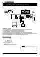
3 CONNECTIONS 3-1 Recording video signals from a camera This section describes how to connect a camera and record camera signals. When more than one camera is connected, the cameras must be synchronized. Multi-camera connections are discussed in the next section.
3 CONNECTIONS (contd.) 3-2 Connecting more than one camera (using an external switcher) When an external switcher is connected to the [CAMERA IN] connector of this unit, images from multiple cameras can be recorded. Select the camera image with the switcher. ● For a connectable multiplexer (switcher), consult your JVC dealer.
3 CONNECTIONS (contd.) 3-3 Connecting signal input/output terminals [CAM SW OUT] camera switching signal output terminal To control the camera switching timing from this unit. [ALARM IN] alarm signal input terminal Starts alarm or sensor recording when a signal is received. ALARM IN CAM SW OUT COM COM Frame switcher’s camera switching signal input Frame switcher/alarm sensor’s alarm output terminal Reference: "3-2 Connecting more than one camera (using an external switcher)" on page 10.
4 PREPARATION 4-1 Installing a battery DIGITAL VIDEO RECORDER VR-510U POWER TIMER CANCEL MENU DISPLAY SEARCH PLAY STILL SELECT REV WARNING REC SLEEP STOP 1. Turn the [POWER] switch OFF. REC FWD CLOCK RESET/ CLEAR OPE. LOCK EXECUTE ON SKIP/ALARM SEARCH 2. Open the battery cover. While pushing down the pawl in the upper section of the battery cover, pull it towards you to open the cover. 3. Install a battery. Install the provided battery (CR2032) with the + side facing you. 4.
4 PREPARATION (contd.) 4-3 Setting the date and time Jog dial Shuttle dial MENU SELECT REV FWD 2. Display the main menu. Press the [MENU] button to display the main menu screen. Refer to “Jog/shuttle dial operation” on page 16 and set the jog dial function with the shuttle dial operation. SEARCH EXECUTE SKIP/ALARM SEARCH 3. Characters selected with the cursor are highlighted. J OG 1. Turn the power ON. Check the connections and press the [POWER] switch ON. 3. Display the [CLOCK SET] screen.
5 ON-SCREEN DISPLAY/MENU SWITCHES 5-1 On-screen display Date, time, number of alarms and remaining hard disk capacity can be displayed on-screen. Date and time data can be recorded together with the video signals by setting the
5 ON-SCREEN DISPLAY/MENU SWITCHES (contd.) 5-2 Menu switches Menu flow Main menu screen [ MEN U ] J OG ¥ C LOC K S E T C N SC R E E N F . D I S P MO D E DV R MODE EXT MODE A LAR M S ENSOR MODE BUZZ E R P ROGR A M T I ME R HO L I D A Y S E T S Y ST E M L I ST M D 1 Y 1 H 2001 DAYL I GHT [ E X T MOD E ] JOG [ C LO C K S E T ] 1 . R E C M ODE 2 . H DD F U L L M 0 : 00 SAV I N G J OG OF F OF F OU T [ A L A RM S ENS OR MOD E ] 1 . R E C M OD E 2 .
5 ON-SCREEN DISPLAY/MENU SWITCHES (contd.) 5-2 Menu switches (contd.) Jog/shuttle dial operation Use the jog/shuttle dial to set the menu or search menu items. SELECT REV FWD Shuttle dial operation Shuttle dial Jog dial JOG f 1. Menu or search screen Turn the shuttle dial to the right or left so that it passes the SELECT position. Main menu or search menu screen • Turning the shuttle dial displays the selected main menu or search menu screen for menu switch setting.
5 ON-SCREEN DISPLAY/MENU SWITCHES (contd.) 5-2 Menu switches (contd.) Display Jog dial Shuttle search dial [MENU] button DIGITAL VIDEO RECORDER VR-510U POWER TIMER CANCEL MENU SELECT REV WARNING REC SLEEP STOP DISPLAY SEARCH PLAY STILL REC FWD CLOCK RESET/ CLEAR EXECUTE OPE. LOCK ON SKIP/ALARM SEARCH [DISPLAY] button Connect the [MONITOR OUT] connector to the monitor’s video input connector. [ MEN U ] J OG C LOC K S E T C N SC R E E N F .
5 ON-SCREEN DISPLAY/MENU SWITCHES (contd.) 5-2 Menu switches (contd.) Setting Connect the [MONITOR OUT] connector to the monitor’s video input connector. 3. [ MEN U ] J OG 1. Turn this unit and the monitor ON. Data is displayed on-screen. C LOC K S E T C N SC R E E N F . D I S P MO D E DV R MODE EXT 2. Display the main menu screen. Press the [MENU] button to display the main menu screen.
5 ON-SCREEN DISPLAY/MENU SWITCHES (contd.) 5-3 Menu switch details The setting in [ Setting item ON SCREEN MODE ] is the factory setting. Menu switch ON SCREEN POSITION [UP-L] UP-R LOW-L LOW-R Description Sets the on-screen display position. DAY [ON] OFF Sets the on-screen day/month/year display. ON : Displayed. OFF: Not displayed. TIME [ON] OFF Sets on-screen clock display ON : Displayed. OFF: Not displayed. ALARM COUNT [ON] OFF Sets the on-screen alarm/sensor number display. ON : Displayed.
5 ON-SCREEN DISPLAY/MENU SWITCHES (contd.) 5-3 Menu switch details (contd.) Setting item DVR MODE Menu switch Setting value Description AUDIO REC [ON] OFF Sets whether or not audio signals are recorded during recording. ON : Records audio signals. OFF: Does not record audio signals. *When menu switch is set to "1/5" or"1/10", this item will be automatically set to "OFF". POWER ON REC ON [OFF] Sets whether or not recording re-starts when the power is restored after a power failure.
5 ON-SCREEN DISPLAY/MENU SWITCHES (contd.) 5-3 Menu switch details (contd.) Setting item ALARM/ SENSOR MODE BUZZER UTILITY Menu switch Setting value Description REC MODE [OFF] ALARM SENSOR Sets the alarm or sensor recording. OFF : Does not execute alarm/sensor recording. ALARM : Executes alarm recording. SENSOR : Executes sensor recording. Reference: “6-4 Alarm recording” on page 28 and “6-5 Sensor recording” on page 29.
6 RECORDING 6-1 Basic operation Jog dial Shuttle search dial [MENU] button DIGITAL VIDEO RECORDER VR-510U POWER TIMER CANCEL MENU DISPLAY SEARCH PLAY STILL SELECT REV WARNING REC SLEEP STOP REC FWD CLOCK RESET/ CLEAR EXECUTE OPE. LOCK ON SKIP/ALARM SEARCH [STILL] button [REC] button [STOP] button Operation Major menu switches 1. Turn the power ON. Check the connections and set the [POWER] switch on the rear panel to ON. 2. Set the menu switches. Set the menu switches as required.
6 RECORDING (contd.) 6-2 Program timer recording Two types of program timer recording are available: weekly and daily. [CANCEL] button Jog dial [MENU] button Shuttle search dial [TIMER] button DIGITAL VIDEO RECORDER VR-510U POWER TIMER CANCEL MENU DISPLAY SEARCH PLAY STILL SELECT REV WARNING REC SLEEP STOP FWD REC CLOCK RESET/ CLEAR EXECUTE OPE. LOCK ON SKIP/ALARM SEARCH ( ) TIMER indication Weekly timer Select with JOG – +. 4.
6 RECORDING (contd.) 6-2 Program timer recording (contd.) [CANCEL] button Jog dial [MENU] button Shuttle search dial [TIMER] button DIGITAL VIDEO RECORDER VR-510U POWER TIMER CANCEL MENU SELECT REV WARNING REC SLEEP STOP DISPLAY SEARCH PLAY STILL FWD REC CLOCK RESET/ CLEAR EXECUTE OPE. LOCK ON SKIP/ALARM SEARCH ( ) TIMER indication Timer-recording for 24 hours or more Example: High-quality recording at 1/5 frame per second programmed from 9:00 p.m. Saturday to 8:00 a.m.
6 RECORDING (contd.) 6-2 Program timer recording (contd.) [CANCEL] button Jog dial [MENU] button Shuttle search dial [TIMER] button DIGITAL VIDEO RECORDER VR-510U POWER TIMER CANCEL MENU SELECT REV WARNING REC SLEEP STOP DISPLAY SEARCH PLAY STILL FWD REC CLOCK RESET/ CLEAR EXECUTE OPE. LOCK ON SKIP/ALARM SEARCH ( ) TIMER indication Daily timer 4.
6 RECORDING (contd.) 6-2 Program timer recording (contd.) Canceling a timer recording program Changing timer program settings Operation in the Timer Recording Standby mode 1. Display the [PROGRAM TIMER] screen. Display the [PROGRAM TIMER] screen. For details, refer to “Setting” on page 18. 2. Select the program to be changed. Set the cursor on the program to be changed with [JOG ]. 3. Select the item to change. Set the blinking cursor on the item you want to change with [JOG p[]. 4.
6 RECORDING (contd.) 6-3 Holiday timer recording Timer recording can be performed on specified days during the year such as holidays. When holiday timer recording and programmed timer recording overlap, holiday timer recording has a priority. [CANCEL] button Jog dial [MENU] button Shuttle search dial [TIMER] button DIGITAL VIDEO RECORDER VR-510U POWER TIMER CANCEL MENU SELECT REV WARNING REC SLEEP STOP DISPLAY SEARCH PLAY STILL FWD REC CLOCK RESET/ CLEAR EXECUTE OPE.
6 RECORDING (contd.) 6-4 Alarm recording When an alarm signal is received (via the rear panel [ALARM IN] terminal) during recording, the alarm recording mode set with the menu switch is automatically engaged. Jog dial [CANCEL] button [MENU] button Shuttle search dial DIGITAL VIDEO RECORDER VR-510U POWER TIMER CANCEL MENU SELECT REV WARNING REC SLEEP STOP DISPLAY SEARCH PLAY STILL FWD REC CLOCK RESET/ CLEAR EXECUTE OPE. LOCK ON SKIP/ALARM SEARCH [REC] button [ALARM/SENSOR] screen 3.
6 RECORDING (contd.) 6-5 Sensor recording When an alarm signal is input to the rear panel [ALARM IN] terminal in the Stop mode, sensor recording starts in the mode set with the menu switch. Jog dial [CANCEL] button [MENU] button Shuttle search dial DIGITAL VIDEO RECORDER VR-510U POWER TIMER CANCEL MENU DISPLAY SEARCH PLAY STILL SELECT REV WARNING REC SLEEP STOP REC FWD CLOCK RESET/ CLEAR OPE.
6 RECORDING (contd.) 6-6 Recording with an external activation signal Recording can be started and stopped externally when an activation signal is input to the rear panel [EXT REC IN] terminal. 1. POWER ON CAMERA IN 1 AUDIO IN I O OFF Connection RS-232C 1 1 2 2 CAM SW ALARM ALARM CLOCK EXT OUT IN1 SPARE RESET RESET IN REC IN HDD CLOCK SPARE SPARE COM RESET OUT FULL OUT COM SIGNAL GND AC IN 120 V 50 Hz / 60 Hz AUDIO OUT MONITOR OUT 1. Connect an external control device.
7 PLAYBACK AND SPECIAL-EFFECTS PLAYBACK 7-1 Basic operation DIGITAL VIDEO RECORDER VR-510U POWER TIMER CANCEL MENU SELECT REV WARNING REC SLEEP STOP DISPLAY SEARCH PLAY STILL FWD REC CLOCK RESET/ CLEAR EXECUTE OPE. LOCK ON SKIP/ALARM SEARCH [STOP] button [STILL] button [PLAY] button Operation Memo: 1. Turn the power ON. Check the connections and set the [POWER] switch on the rear panel to ON. 2. Start playback. Press the [PLAY] button.
7 PLAYBACK AND SPECIAL-EFFECTS PLAYBACK (contd.) 7-2 Jog/shuttle playback Jog playback allows you to view a recording one frame at a time while shuttle playback lets you vary playback speed. These functions are useful when you want to find a specific scene or examine recorded images in more detail. The shuttle dial is the outer ring and the jog dial is the inner dial.
7 PLAYBACK AND SPECIAL-EFFECTS PLAYBACK (contd.) 7-3 Skip search When the search distance is specified in the menu, the skip search is possible. This function lets you skip quickly through a series of events and check each one briefly for alarm points. Jog dial Shuttle search dial DIGITAL VIDEO RECORDER VR-510U POWER TIMER CANCEL MENU DISPLAY SEARCH PLAY STILL SELECT REV WARNING REC SLEEP STOP FWD REC CLOCK RESET/ CLEAR EXECUTE OPE.
7 PLAYBACK AND SPECIAL-EFFECTS PLAYBACK (contd.) 7-3 Skip search (contd.) Jog dial Shuttle search dial DIGITAL VIDEO RECORDER VR-510U POWER TIMER CANCEL MENU DISPLAY SEARCH PLAY STILL SELECT REV WARNING REC SLEEP STOP REC FWD CLOCK RESET/ CLEAR EXECUTE OPE. LOCK ON SKIP/ALARM SEARCH [STOP] button [STILL] button [PLAY] button [SKIP SEARCH·EXECUTE] button Event search Alarm search 1. Turn the power ON. Check the connections and set the [POWER] switch on the rear panel to ON. 1.
7 PLAYBACK AND SPECIAL-EFFECTS PLAYBACK (contd.) 7-4 Alarm or day/time direct search You can access a recording by specifying the alarm number or date/time. 2. [ S EARC H M ENU ] J OG The cursor blinks. Alarm direct search 1. Turn the power ON. Check the connections and set the [POWER] switch on the rear panel to ON. 2. Display the [SEARCH MENU] button. Press the [SEARCH] button to display the [SEARCH MENU] screen on the monitor.
8 HARD DISK CONTROL 8-1 Hard disk maintenance When power is interrupted (disconnection, power failure, etc.) in the Record mode or Sensor Record Standby mode, the recording information on the hard disk may be damaged. This may cause problems in recording and playback. To repair the hard disk, two disk scan functions ( and ) are available. ● If is set to “ON”, the disk is scanned automatically whenever the power is turned on or restored.
8 HARD DISK CONTROL (contd.) 8-1 Hard disk maintenance (contd.) When the hard disk is full, re-format it in the standard or extended mode. Jog dial [MENU] button Shuttle search dial DIGITAL VIDEO RECORDER VR-510U POWER TIMER CANCEL MENU DISPLAY SEARCH PLAY STILL SELECT REV WARNING REC SLEEP STOP FWD REC CLOCK RESET/ CLEAR EXECUTE OPE. LOCK ON SKIP/ALARM SEARCH [SKIP SEARCH·EXECUTE] button Erasing & formatting 1. [ MEN U ] 1. Display the [UTILITY] screen.
9 TROUBLESHOOTING 9-1 Error indication Error indications are displayed on-screen whenever there is an abnormality with signal reception, the hard disk, or the menu settings (such as timer recording setting errors). On-screen indication/ [WARNING] indication Cause Possible solution Page reference “HDD ERROR” The [WARNING] indication lights. The hard disk is not functioning properly. Consult your nearest JVC dealer. – “HDD FULL” The [WARNING] indication lights.
9 TROUBLESHOOTING (contd.) 9-2 No error indication Problem Cause Possible solution Page reference No power is supplied. ● The power cord may be disconnected. ● Connect the provided power cord to a 120 V AC outlet. 9 Operation buttons such as [REC] and [PLAY] do not respond when pressed. ● The Operation Lock mode may be engaged. ● Release the Operation Lock mode. 20 No picture is shown during playback. ● The monitor may not be properly connected.
10 RS-232C INTERFACE 10-1 Specifications 9-pin connector specifications Pin No.
10 RS-232C INTERFACE (contd) 10-2 Protocols and commands (contd.
10 RS-232C INTERFACE (contd.) 10-3 Commands Preparation Commands Connect the RS-232C connector. 91H Operation commands The commands to operate this unit are shown below. When the signal is received normally, this unit returns ACK (0Ah) and is ready for the operation corresponding to the command received. e.g.
10 RS-232C INTERFACE (contd.) 10-3 Commands (contd.) Setup commands Commands Sets switches on this unit. When the signal is received normally, this unit returns ACK (0Ah) and is ready to execute the command received. Commands 74H 89H %%H %%H %%H TXD 89H 0AH 0AH 0AH 0AH RXD 1 byte Bit 7 6 Description ON SCREEN SELECT: Switches the on-screen display details. 5~3 %%H TXD 74H 0AH 0AH RXD 1 byte Bit 7 6 5 4 3 2 1 0 86H Description DVR SETTING: Sets the DVR-related status data.
10 RS-232C INTERFACE (contd.) 10-3 Commands Commands 8AH SENSE commands Description ALARM/SENSOR MODE SET: Sets alarm/sensor recording-related data %%H %%H %%H TXD 8AH 0AH 0AH 0AH 0AH RXD 2 bytes Bit 7 6~5 4 5-bit 0 1 0 PRESENSOR REC DURATION 10 sec. 30 sec. 60 sec.
10 RS-232C INTERFACE (contd.) 10-3 Commands (contd.) Commands B9H Description DVR SETTING SENSE: Returns settings status.
10 RS-232C INTERFACE (contd.) 10-3 Commands Commands BEH Description TXD BEH 3%H RXD 3%H 3%H Month BFH 3%H 3%H Day D6H 3%H 3%H Hour 3%H 1 st byte 3%H Year 3%H Minutes 1 byte Bit 7 6 5 4 3 2 1 3%H Seconds HDD FORMAT SENSE: Returns hard disk format information. TXD D0H %%H RXD 1st byte 1 byte D1H 0 Status details 00H 01H 02H DEVICE TYPE: Returns the connected device type.
11 OTHERS 11-1 Recording time The table below shows the recording time in each picture quality mode. Actual recording time may differ depending on the hard disk conditions so you should use these figures as guidelines only.
11 OTHER (contd.) 11-2 Signal input/output terminals Signal level Terminals [CAM SW OUT] camera switching signal output Remarks Open collector output (When menu switch is set to "30") Ref.Sig 1st field 2nd field 1st field 2nd field CAN SW OUT GND 5 ms [ALARM IN 1] alarm signal input Ground input High voltage = 5 V Min. 400 ms [ALARM RESET] alarm signal reset input Min.
11 OTHER (contd.) 11-3 Specifications Picture compression : MPEG 2 (1 frame only) Recording capacity : 80 GB (can be increased up to 160 GB) Power supply : AC 120 V, 60 Hz Power consumption : 34 W Allowable operation temperature : 5˚C to 40˚C Allowable storage temperature : – 20˚C to 60˚C Allowable operation humidity : 30% to 80% Weight : Approx. 6.
VR-510U DIGITAL VIDEO RECORDER R VICTOR COMPANY OF JAPAN, LIMITED is a registered trademark owned by VICTOR COMPANY OF JAPAN, LTD. is a registered trademark in Japan, the U.S.A., the U.K. and many other countries.