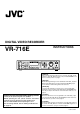
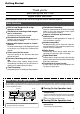
DIGITAL VIDEO RECORDER INSTRUCTIONS VR-716E CANCEL 1 2 ALARM SENSOR 5 6 3 4 ALARM SENSOR 7 8 9 10 ALARM SENSOR 13 14 ALARM SENSOR 15 1 HDD MENU REV REC STOP PLAY OPERATE FWD TIMER DISPLAY SEQUENCE MULTI 11 SEARCH LOCK OUT VIDEO AUDIO EXECUTE STILL 16 SKIP [ENGLISH] The instruction manual in pdf version is stored as ‘VR-716E_en.pdf’ under the ‘VR-716E_Manual’ folder in the provided CD-ROM. For reference method, please see page 3.
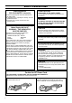
SAFETY PRECAUTIONS POWER SYSTEM Connection to the mains supply Warning Notice FOR YOUR SAFETY (Australia) This unit operates on voltage of 220 V to 240 V AC, 50 Hz/60 Hz. 1.Insert this plug only into effectively earthed threepin power outlet. 2.If any doubt exists regarding the earthing, consult a qualified electrician. 3.Extension cord, if used, must be three-core correctly wired. WARNING: TO REDUCE THE RISK OF FIRE OR ELECTRIC SHOCK, DO NOT EXPOSE THIS APPLIANCE TO RAIN OR MOISTURE.
SAFETY PRECAUTIONS WARNING WARNING This is a Class A product. In a domestic environment this product may cause radio interference in which case the user may be required to take adequate measures. For PLUGGABLE EQUIPMENT, the socket outlet shall be installed near the equipment and shall be easily accessible. 䡵 Place of storage and use Please avoid storing or using this DVR in the following places: • Extremely hot or cold places beyond the allowable temperature for operation (5˚C - 40˚C).
Table of Content Getting Started Connecting to a PC Table of Content ....................................................................... 4 Main Features ........................................................................... 5 Precautions .............................................................................. 6 Names and Functions .............................................................. 7 System Connection (When Connecting 16 Cameras) ........ 14 Mounting to a Rack ..................
Getting Started Thank you for purchasing this VR-716E Digital Video Recorder. In the subsequent sections of this manual, this equipment shall be referred to as VR-716. Main Features Built-in hard disk drive with a high capacity of 160 GB Simultaneous recording of 400 images / sec in 16 channels Alarm/Sensor Recording Recording up to 400 images/second.
Getting Started (continued) Precautions 䡵 Do not stack up the equipment to prevent temperature within from rising. 䡵 Do not stand this equipment vertically during use. 䡵 Handle this equipment with care. Do not subject it to physical shock. 䡵 Do not expose the equipment to physical shock during transport. In particular, do not move the equipment during recording or playback. 䡵 This product utilizes the open source software. Refer to the instruction on page 104 to display the precise information.
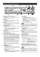
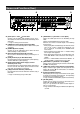
Names and Functions (Front) 5 4 3 CANCEL 1 2 ALARM SENSOR 5 6 3 4 ALARM SENSOR 7 8 9 10 ALARM SENSOR 13 14 1 ALARM SENSOR LOCK DISPLAY 15 STOP PLAY OUT VIDEO AUDIO EXECUTE STILL 16 6 OPERATE FWD TIMER REC 1 HDD MENU REV SEQUENCE MULTI 11 SEARCH 2 SKIP 7 1 [OPERATE] Button and Operate LED To turn off the power, press the button continuously for about 2 seconds.
Getting Started (continued) Names and Functions (Front) $ % CANCEL 1 2 ALARM SENSOR 5 6 3 4 ALARM SENSOR 7 8 9 10 ALARM SENSOR 13 14 1 ALARM SENSOR ^ REC STOP PLAY OPERATE FWD LOCK OUT VIDEO AUDIO EXECUTE STILL 16 SKIP & ! [HDD] LED Lights up when the built-in hard disk drive is in operation. @ [MENU] Button Press this button to display the menu screen or to return from the menu to the main screen.
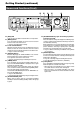
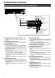
Names and Functions (Rear) ¤ ⁄ ) AUDIO IN 1 2 3 4 5 6 7 8 9 10 11 12 13 14 15 16 1 4/ 16 5 8 VIDEO IN THRU OUT SCSI AUDIO OUT RS-232C UPS LAN 1 2 CAUTION VIDEO OUT 1 RISK OF ELECTRIC SHOCK DO NOT OPEN 2 AVIS:RISQUE DE CHOC ELECTRIQ 1 3 5 7 9 11 13 2 4 6 8 10 12 14 ALARM ‹ › fi ) [AC IN (220 V - 240 V fl ‡ ° · )] Power Inlet Connect using the power cord supplied to an AC 220 V 240 V outlet. The main unit will turn on automatically when connected.
Getting Started (continued) Names and Functions (Signal In/Out Terminal) (Rear) AUDIO IN 1 2 3 4 5 6 7 8 9 10 11 12 13 14 15 16 VIDEO IN THRU OUT SCSI AUDIO OUT RS-232C UPS LAN 1 2 CAUTION VIDEO OUT 1 RISK OF ELECTRIC SHOCK DO NOT OPEN 2 AVIS:RISQUE DE CHOC ELECTRIQ 1 4/ 16 1 3 5 7 2 4 6 8 11 13 15 RST COM IN 12 14 16 OUT WAR RST REC COM IN CLK SER 5 8 OUT OUT OUT AC IN (220V–240V ) SIGNAL GND EXT REC 9 10 ALARM 9 12 13 16 EE OUT 2ALARM RESET 3CLOCK RESE
Terminal Signal Level Remarks Grounded Input (44 k¸) 5V High Voltage = 5 V Low Voltage = 0 V [CLOCK RESET IN] 22k Min. 500 ms ¸ or less. Ensure that the impedance at the output is 10 k¸ IN 22k SET Open Collector High Voltage = 5 V Low Voltage = 0 V [CLOCK RESET OUT] 1s 22k OUT SET 22k Grounded Input (44 k¸) 5V High Voltage = 5 V Low Voltage = 0 V [ALARM IN] Min. 400 ms 22k ¸ or less. Ensure that the impedance at the output is 10 k¸ SET During Alarm Recording High Output (4.
Getting Started (continued) Names and Functions (Front Display) CANCEL 1 2 ALARM SENSOR 5 6 3 4 ALARM SENSOR 7 8 9 10 ALARM SENSOR 13 14 ALARM SENSOR 15 1 2 3 4 5 1 6 HDD MENU REV DISPLAY SEQUENCE MULTI 11 SEARCH REC STOP PLAY LOCK OUT VIDEO AUDIO EXECUTE STILL 16 7 OPERATE FWD TIMER SKIP 8 9 0 1 Operation Mode Indicator 2 _ < I < << = ==
Names and Functions (Front Display) 0 Counter/Setting Display Press the [DISPLAY] button 8 on the front panel to switch between the clock display, date display, remaining space display and record setting display. 䡵 Clock Display: Example > 12:34:56, 1 March When in the Play mode, display of recording time on the playback screen is not possible.
Installation and Preparation System Connection (When Connecting 16 Cameras) Connection with up to 16 cameras is possible with VR-716’s switcher. • Perform recording/playback by connecting to 16 cameras. • Checking recorded images at Monitor 1 and live camera images on Monitors 2 ~ 5 at the same time. • Execution of alarm recording upon receiving signals from the alarm sensor.
Mounting to a Rack Make use of the rack-mounting bracket provided when mounting VR-716 to the EIA rack. 1 1. Mount the rack-mounting bracket to VR-716 us- 3 ing Screw 1 Rack-mounting Bracket • Fasten the two sides of VR-716 using the 4 screws provided (M4 x 10 mm). 3 1 2. Remove Screw 2 (4 corners) on the foot stand at the bottom surface of the equipment 2 (4 corners) • Remove the foot stand. Caution • Do not place any object on VR-716 that has been mounted onto the rack.
Installation and Preparation (continued) Setting the Date/Time Onscreen Setting Using the Monitor Screen Set the date and time on the monitor screen. 1. SEARCH 䡵 TIME ZONE Setting 1. Press the [MENU] button HDD MENU REV OPERATE FWD LOCK OUT VIDEO AUDIO EXECUTE • This displays the “MAIN MENU/OPERATION MENU” screen on the monitor. MENU SKIP 2.3. 4. 3. 2.
U 䡵 5. 10. SEARCH Clock Setting 5. Press the [MENU] button HDD MENU REV OPERATE FWD LOCK OUT VIDEO AUDIO EXECUTE • This displays the “MAIN MENU/OPERATION MENU” screen on the monitor. MENU SKIP 6.7.8.9. 7.8. 6. Select the “CLOCK SET” item using [ / Menu Screen MAIN MENU/OPERATION MENU CLOCK SET ONSCREEN MODE FDP/BUZZER REC MODE CAMERA TITLE OPERATION/EXT REC MONITOR DISPLAY ALARM SENSOR MODE PROGRAM TIMER NETWORK DISK UTILITY/MAINTENANCE ] • Move the cursor to select. 7.
Installation and Preparation (continued) Setting the Date/Time Setting Using the Front Display Set the date/time on the front display of VR-716. Caution longer • Ensure to set the TIME ZONE before setting the Date/ Time. CANCEL SEARCH HDD MENU REV OPERAT FWD TIMER DISPLAY 1. Press the [DISPLAY] button for 2 seconds or LOCK • The “D” (Day) item on the front display will start to blink. DISPLAY Note • Date/Time setting is disabled when VR-716 is in the Recording mode.
Onscreen Display VR-716 allows the onscreen display of Date/Time, Alarm (Sensor) No. and the operational state on the monitor. Changing Position of Onscreen Display 1. Press and hold the [EXECUTE] button for a while Day-Month-Year Day of the Week 01-03-2003 SA 12:34:56 60% AL AL*3 Time (24-hour Display) Alarm (Sensor) Detection (Blinks) Playback Direction (Operational State) Alarm (Sensor) No. SLOW • The monitor screen switches to the Onscreen Display Position Adjustment mode.
Menus Menu Flow Chart Menu Screen MAIN MENU/OPERATION MENU CLOCK SET ONSCREEN MODE FDP/BUZZER REC MODE CAMERA TITLE OPERATION/EXT REC MONITOR DISPLAY ALARM SENSOR MODE PROGRAM TIMER NETWORK DISK UTILITY/MAINTENANCE “CLOCK SET” Menu CLOCK SET D 15 M 07 Y 2003 “CAMERA TITLE” Menu H 12 CAMERA TITLE 1.BLOCK 2.CAMERA 1 3.CAMERA 2 4.CAMERA 3 5.
“PROGRAM TIMER” Menu PROGRAM TIMER 1.WEEKLY TIMER 2.DATE TIMER 3.
Menus (continued) Changing Menu Settings Changing Initial Settings Change the VR-716 preset values (Factory settings) during purchase according to its use. Connect the monitor for which the menu screen is to be displayed to the [VIDEO OUT] terminal. (☞ Page 33) 1. Press the [MENU] button • This displays the “MAIN MENU/OPERATION MENU” screen on the monitor. 1.6.
“ONSCREEN MODE” Menu [ ● ] are factory settings. Item Settings Description “DATE/TIME” ● “ON” “OFF” For setting the Day/Month/Year and clock’s onscreen display. “ON” : Date/time displayed. “OFF” : Date/time not displayed. “PLAYBACK MODE” ● “ON” “OFF” For setting the onscreen display of the Playback mode. “ON” : Playback mode displayed. “OFF” : Playback mode not displayed. “TITLE” ● “ON” “OFF” For setting the onscreen display of camera channel titles. “ON” : Title displayed.
Menus (continued) “BUZZER” Menu [ ● ] are factory settings. Item Settings Description “HDD FULL” “ON” ● “OFF” For setting whether to sound the buzzer when the hard disk has no more space during recording. “ON” : The buzzer sounds. “OFF” : The buzzer does not sound. “ALARM/SENSOR” “ON” ● “OFF” For setting whether to sound buzzer during alarm/sensor recording. “ON” : The buzzer sounds. “OFF” : The buzzer does not sound. “WARNING” “ON” ● “OFF” For setting whether to sound buzzer when error occurs.
“CAMERA TITLE” Menu [ ● ] are factory settings. (Setting is disabled when in the Recording mode.) Item “CAMERA 1” ~ “CAMERA 16” Settings ********** Description Camera Channels 1 - 16 can be named separately. ☞ Page 72 ‘Setting a Title for Each Camera Channel Screen’ “OPERATION” Menu [ ● ] are factory settings. (Setting is disabled when in the Recording mode.) Item Settings Description “RECOVERY REC” ● “OFF” “PRIOR STATE” “NORMAL REC” For setting whether to perform Recovery Recording.
Menus (continued) “MONITOR DISPLAY” Menu [ ● ] are factory settings. Item “EE OUT1 - 4/ -16” Settings Description ● “1-4” “1-16” For setting the screen during output of camera images in VR-716 to the [EE OUT 1-4/-16] terminal. “1-4” : Images displayed in quad picture. “1-16” : Images displayed in 16 split pictures.
“ALARM/SENSOR MODE” Menu This menu is used for specifying settings related to alarm or sensor recording. Alarm/sensor inputs are either received via the [ALARM IN] terminal at the rear panel of VR-716 or via Motion Detect. [ ● ] are factory settings. (Setting is disabled when in the Recording mode.) Item Settings Description “BLOCK” ●1 2 3 4 For selecting the camera channel block for which alarm or sensor recording settings are to be specified. 1 : Sets to Camera Channels 1 - 4.
Menus (continued) “ALARM/SENSOR MODE” Menu (continued) [ ● ] are factory settings. (Setting is disabled when in the Recording mode.) Item Settings Description “EXT INPUT OPERATING MODE” ● “OFF” “ON” “NORMAL” “TIMER” For setting alarm or sensor recording actions for the signal input/output terminal [ALARM IN] of VR-716. “OFF” : Alarm/sensor recording not activated. “ON” : Alarm/sensor recording activated.
“PROGRAM TIMER” Menu Setting is disabled when in the Recording mode. Item Settings “WEEKLY TIMER” Description Opens the “WEEKLY TIMER” screen in the “PROGRAM TIMER” for setting. ☞ Page 50 ‘Record Programming Using the Program Timer (Weekly Timer)’ “START”/ “END” DAY “SUN”, “MON”, “TUE”, “WED”, “THU”, “FRI”, “SAT”, “DAY” Starts/Ends recording at a specific time every week/day. For setting the day of the week for which recording starts/ends (or to start/end recording on a daily basis).
Menus (continued) “PROGRAM TIMER” Menu (continued) [ ● ] are factory settings. Item Settings “DATE TIMER” Description For executing the recording of a program on a specific date. Opens the “DATE TIMER” screen in the “PROGRAM TIMER” Menu for setting. ☞ Page 52 ‘Record Programming Using the Program Timer (Date Timer)’ “START”/ “END” TIME (HOUR) 00 ~ 23 For setting the starting/ending time (in units of hours) of the timer.
“NETWORK” Menu [ ● ] are factory settings. (Setting is disabled when in the Recording mode.) Settings Item Description “HOST NAME” vr716 For setting the display name of VR-716 when it is connected to the network. ☞ Page 96 ‘Changing Network Settings of VR-716 from PC’ “METHOD” ● “STATIC” “DHCP” “OFF” For selecting the method of setting the IP address. “STATIC” : Select this when connecting to the network without using the DHCP server.
Routine Uses Viewing Live Camera Images When connecting the monitor to the [EE OUT] terminal Only live images currently displayed can be viewed on the monitor that is connected to the [EE OUT] terminal. Playback of recorded images and display of menu screens are not possible.
When connecting the monitor to the [VIDEO OUT] terminal Display of live images, playback of recorded images and display of menu screens on the monitor are possible when it is connected to the [VIDEO OUT] terminal.
Routine Uses (continued) Viewing Live Camera Images Setting Time Interval for Switching Displays in the Single Picture Mode This enables the monitor to display images from Camera 1 ~ Camera 16 by switching from one camera to another according to the preset time interval. Connect the monitor to the [VIDEO OUT] terminal. • Follow procedures in ‘Changing Menu Settings’ on page 22 to display the “MONITOR DISPLAY” Menu and the “SINGLE PICTURE MODE” screens. 1.5.
Setting Time Interval for Switching Displays in the Quad Picture Mode Monitor will display images of each block (“BLOCK 1”: “CAMERA 1” ~ “CAMERA 4”, “BLOCK 2”: “CAMERA 5” ~ “CAMERA 8”, “BLOCK 3”: “CAMERA 9” ~ “CAMERA 12”, “BLOCK 4”: “CAMERA 13” ~ “CAMERA 16”) in quad picture by switching from one block to another. 1. Press the [MENU] button Connect the monitor to the [VIDEO OUT] terminal. MENU 1.4. CANCEL SEARCH HDD MENU REV OPERATE FWD TIMER 2.
Routine Uses (continued) Recording Camera Images Recording in the Normal Mode 1. Press the [MENU] button 1.2. L SEARCH HDD MENU REV • Display the “REC MODE” Menu by following the procedures in ‘Changing Menu Settings’ on page 22 and specify settings for menu items required for recording. OPERATE FWD R LOCK AY MENU OUT VIDEO AUDIO EXECUTE SKIP ● Main menu items related to recording: CANCEL SEARCH 6 8 TIMER REC MODE 1.BLOCK 2.CAMERA 1 3.CAMERA 2 4.CAMERA 3 5.CAMERA 4 6.FRAME RATE 7.
Repeat Recording (Repeat Record Feature) VR-716 comes equipped with a Repeat Record feature that returns to the start point and overwrites old data when there is insufficient hard disk space. ☞ Page 112 ‘Repeat Record’ 1. Press the [MENU] button 1.4. L SEARCH • Follow procedures in ‘Changing Menu Settings’ on page 22 to display the “OPERATION/EXT REC” Menu. HDD MENU REV MENU OPERATE OPERATION/EXT REC [ OPERATION ] 1.RECOVERY REC 2.REPEAT REC 3.LANGUAGE SELECTION 4.WATER MARK 5.
Routine Uses (continued) Viewing Recorded Images Playing Back Recorded Images Play back the recorded images. To do so, search according to the date of the image to be played back using “DATE/TIME SEARCH” (☞ page 40) or according to the time when alarm/sensor signals are received using the “ALARM/SENSOR SEARCH” feature (☞ page 41). Connect the monitor for viewing the playback image to the [VIDEO OUT] terminal. 1. Search for the image to view • Search according to the date of the image.
Viewing Recorded Images in the Split Screen Mode 1. Press the [PLAY] button Connect the monitor for viewing the playback image to the [VIDEO OUT] terminal. • The playback mark [<] on the front display lights up and playback starts. Front Display PLAY C 1 2 ALARM SENSOR 5 6 3 4 ALARM SENSOR 7 8 9 10 ALARM SENSOR 13 14 11 1 ALARM SENSOR 15 16 D SEQUENCE MULTI 2.3. REC STOP PLAY 2. Press the ‘Camera Selection’ button STILL • Select the camera no.
Routine Uses (continued) Viewing Recorded Images Searching Image According to Date/Time (“DATE/TIME SEARCH”) Connect the monitor for viewing the playback image to the [VIDEO OUT] terminal. 1. Press the [SEARCH] button • This displays the “SEARCH MENU” screen. SEARCH SEARCH MENU 1.SEARCH SETTING 2.DATE/TIME SEARCH 3.ALARM/SENSOR SEARCH 4.SKIP MODE 5.TIME JUMP SETTING LATEST ALARM 1HOUR 1. SEARCH HDD MENU REV 2.
Searching Image According to Alarm/Sensor Data (“ALARM/SENSOR SEARCH”) Connect the monitor for viewing the playback image to the [VIDEO OUT] terminal. 1. Press the [SEARCH] button • This displays the “SEARCH MENU” screen. 1. SEARCH SEARCH HDD MENU REV SEARCH MENU 1.SEARCH SETTING 2.DATE/TIME SEARCH 3.ALARM/SENSOR SEARCH 4.SKIP MODE 5.TIME JUMP SETTING LATEST ALARM 1HOUR OPERATE FWD 2.
Routine Uses (continued) Viewing Recorded Images Adjusting Playback Speed (Jog/Shuttle Playback) Playback speed can be adjusted by turning the jog/shuttle dial. This feature is very useful when searching for a specific screen for viewing.
Viewing Recorded Images in the Skip Mode Connect the monitor for viewing the playback image to the [VIDEO OUT] terminal. 1. 1. Press the [SEARCH] button • This displays the “SEARCH MENU” screen. SEARCH SEARCH MENU 1.SEARCH SETTING 2.DATE/TIME SEARCH 3.ALARM/SENSOR SEARCH 4.SKIP MODE 5.TIME JUMP SETTING SEARCH 4. HDD MENU REV OPERATE FWD LOCK ALARM 1HOUR 2. Press [ ] to select the “SKIP MODE” item OUT VIDEO AUDIO EXECUTE LATEST • Move the cursor to select. SKIP 2. 3. 5. 3.
Routine Uses (continued) Viewing Recorded Images Enlarging the Still Image (Still Image Zoom) Still images can be viewed in an enlarged mode. Connect the monitor for viewing the playback image to the [VIDEO OUT] terminal. CANCEL SEARCH TIMER DISPLAY STOP PLAY • Press the button at the point for which display is to be enlarged. EXECUTE STILL 2.3. • Perform Steps 1 ~ 3 of ‘Playing Back Recorded Images’ on page 38. 2. Press the [STILL] button MENU REV EC 1. Playback the image STILL 4. 3.
5. Press the [STILL] button CANCEL SEARCH MENU REV TIMER DISPLAY EC STOP PLAY EXECUTE STILL (x2 Zoom) • Each time the [STILL] button is pressed, x2 Zoom or x4 Zoom in both vertical and horizontal directions can be selected. STILL 5. 8. 7. 6. (x4 Zoom) 6. Press the [EXECUTE] button • The portion within the Guide Box will be displayed in full screen. EXECUTE Notes • Still image cannot be enlarged when playback screen is in quad.
Routine Uses (continued) Record Programming Using the Program Timer Weekly Timer (For starting recording on a specific day and time on a weekly basis) Execute recording from 8:00 a.m. every Friday ~ 5:00 p.m. every Saturday. 䡵 Recording Mode • Cameras 1 - 4 “FRAME RATE” : “12.5 IPS” “REC QUALITY” : “H” “AUDIO REC” : “A” (ON) • Cameras 5 - 8 “FRAME RATE” : “25 IPS” “REC QUALITY” : “N” “AUDIO REC” : “A” (ON) • Cameras 9 - 12 “FRAME RATE” : “2.
10. 10. SEARCH CANCEL HDD MENU REV OPERA 6. Press [ ] to move cursor to the Hour position under the “END” column, and turn the jog dial to select “17” FWD TIMER LOCK DISPLAY OUT VIDEO EXECUTE • To set the minute value of the ending time, press [ ] to move cursor to the Minute position and adjust by turning the jog dial. STILL SKIP 6.7.8.9. 6.7.8.
Routine Uses (continued) Record Programming Using the Program Timer Weekly Timer (For starting recording on a specific time of the day) Execute recording from 8:00 a.m. ~ 5:00 p.m. everyday. 䡵 Recording Mode • Cameras 1 - 4 “FRAME RATE” : “12.5 IPS” “REC QUALITY” : “H” “AUDIO REC” : “A” (ON) • Cameras 5 - 8 “FRAME RATE” : “25 IPS” “REC QUALITY” : “N” “AUDIO REC” : “A” (ON) • Cameras 9 - 12 “FRAME RATE” : “2.
10. CANCEL 10. SEARCH HDD MENU REV OPERA FWD TIMER 6. Press [ ] and turn the jog dial to set “FRAME RATE”, “REC QUALITY” and “AUDIO REC” LOCK DISPLAY OUT VIDEO EXECUTE STILL SKIP WEEKLY TIMER END CAM1-4 CAM5-8 CAM9-12 CAM13-16 EXEC START REV 6.7.8.9. FWD SUN ** ** ** ** ** ** *** MON ** ** ** ** ** ** *** DAY 08 00 ** 17 00 12.5 HA WED ** ** THU ** ** FRI ** ** SAT ** ** ** ** ** ** DAY ** ** ** 6.7.8.
Routine Uses (continued) Record Programming Using the Program Timer Weekly Timer (For starting recording on a specific day of the week and time) Execute recording from 9:30 a.m. ~ 10:30 p.m. on every Monday, Wednesday and Friday. 䡵 Recording Mode • Cameras 1 - 4 “FRAME RATE” : “12.5 IPS” “REC QUALITY” : “H” “AUDIO REC” : “A” (ON) • Cameras 5 - 8 “FRAME RATE” : “25 IPS” “REC QUALITY” : “N” “AUDIO REC” : “A” (ON) • Cameras 9 - 12 “FRAME RATE” : “2.
10. 10. SEARCH CANCEL HDD MENU REV OPERA FWD TIMER 6. Press [ ] and turn the jog dial to set “FRAME RATE”, “REC QUALITY” and “AUDIO REC” LOCK DISPLAY OUT VIDEO EXECUTE STILL SKIP WEEKLY TIMER REV 6.7.8.9. START END CAM1-4 CAM5-8 CAM9-12 CAM13-16 EXEC DAY 09 30 ** 22 30 15 HA 15 HA 15 HA 15 HA WLY FWD MON ** ** TUE ** ** WED ** ** THU ** ** ** ** ** ** FRI ** ** ** SAT ** ** ** DAY ** ** ** 6.7.8.
Routine Uses (continued) Record Programming Using the Program Timer Date Timer For executing the recording of a program on different dates. Execute recording from 8:00 a.m. ~ 11:00 p.m. on 1 October and 10 October. 䡵 Recording Mode • Cameras 1 - 4 “FRAME RATE” : “8.3 IPS” “REC QUALITY” : “H” “AUDIO REC” : “A” (ON) • Cameras 5 - 8 Do not record • Cameras 9 - 12 “FRAME RATE” : “4.2 IPS” “REC QUALITY” : “B” “AUDIO REC” : – (OFF) • Cameras 13 - 16 Do not record 1.
11. 11. SEARCH CANCEL HDD MENU REV OPER 7. Press [ ] to move cursor to the Hour position under the “END” column, and turn the jog dial to select “23” FWD TIMER LOC DISPLAY OU VIDEO EXECUTE • To set the minute value of the ending time, press [ ] to move cursor to the Minute position and adjust by turning the jog dial. L SKIP 7.8.9.10. 7.8.9. REV FWD DATE TIMER START END CAM1-4 CAM5-8 CAM9-12 CAM13-16 E X E C 08 00 23 00 * * * * * * * * * * * * 9. 1. 01 - 10 10. 2. 10 - 10 11. 3.
Routine Uses (continued) Record Programming Using the Program Timer Canceling a Record Program 3. CANCEL 1. Press the [MENU] button 1. SEARCH HDD MENU REV OPER • Follow procedures in ‘Changing Menu Settings’ on page 22 to display the “PROGRAM TIMER” Menu and the “WEEKLY TIMER” Menu screens. FWD MENU TIMER LO WEEKLY TIMER START DISPLAY EXECUTE LL SKIP 2. Press [ ] to select the record program to delete 2.
Useful Features Hard Disk Maintenance When power failure occurs while in the Recording mode or Sensor Record Standby mode, or when failure occurs in the recorded data of the hard disk, recording/playback may not function properly. To repair the hard disk, two types of scan disk functions are available on VR-716: • Auto Scan Disk Scans the hard disk automatically upon turning on the power. • Manual Scan Disk Performs manual scanning of the hard disk.
Useful Features (continued) Hard Disk Maintenance Scanning Hard Disk Data (“MANUAL SCAN DISK”) 1. Press the [MENU] button 1. SEARCH • Follow procedures in ‘Changing Menu Settings’ on page 22 to display the “DISK UTILITY/MAINTENANCE” Menu and the “DISK UTILITY” screen. HDD MENU REV OPERATE FWD MENU DISK UTILITY 1.AUTO SCAN DISK 2.MANUAL SCAN DISK 3.DEFRAG DATABASE 4.FORMAT 5.MIRRORING LOCK OUT VIDEO AUDIO EXECUTE SKIP OFF OFF 2. Press [ 2. 4. 3.
Defrag When alarm or sensor recording is performed repeatedly with Repeat Recording set to “ON”, data in the hard disk may become fragmented. Continued use of such data may cause files to split up and recorded into free space, thereby giving rise to fragmentation or decay of data and subsequently slows down the speed extremely during hard disk search. This is where the “DEFRAG DATABASE” feature comes into play in the maintenance of the hard disk.
Useful Features (continued) Initializing the Hard Disk (“FORMAT”) Recording may fail if there is insufficient space on the hard disk. In this case, format the hard disk to create space. 1. Press the [MENU] button 1. CANCEL SEARCH HDD MENU REV OPER FWD TIMER • Follow procedures in ‘Changing Menu Settings’ on page 22 to display the “DISK UTILITY/MAINTENANCE” Menu and the “DISK UTILITY” screen. LOC DISPLAY OUT VIDEO EXECUTE MENU LL DISK UTILITY 1.AUTO SCAN DISK 2.MANUAL SCAN DISK 3.
Hard Disk Mirroring Mirroring refers to recording the same data in the 2 built-in hard disks. In this way, recorded data can be secured even if data in one of the hard disks is damaged. 䡵 Mirroring Setting 1. CANCEL SEARCH 1. Press the [MENU] button HDD MENU REV TIMER DISPLAY OPERATE FWD LOCK OUT VIDEO AUDIO EXECUTE • Follow procedures in ‘Changing Menu Settings’ on page 22 to display the “DISK UTILITY/MAINTENANCE” Menu and the “DISK UTILITY” screen. MENU DISK UTILITY 1.AUTO SCAN DISK 2.
Useful Features (continued) Hard Disk Mirroring (continued) SEARCH HDD MENU REV OPERATE 䡵 Undo Mirroring FWD LOCK OUT VIDEO AUDIO EXECUTE SKIP 1. Turn the jog dial to select “NO” during mirroring setting. MIRRORING BUILT-IN HDD 1 : BUILT-IN HDD 2 : REV 76GB OK 76GB OK FWD NO MIRRORING SETTING 2.3. 1. ALL HDD DATA WILL BE DELETED!! NOW MIRRORING SET [NO] TO CANCEL MIRRORING [EXEC]:CANCEL MIRROR 2. Press the [EXECUTE] button • This displays the “MIRRORING CONFIRMATION” screen.
Series Recording Using 2 or More VR-716 Recorders Recording using 2 or more VR-716 recorders is possible. Once the first VR-716 is full, recording automatically starts at the second VR-716.
Useful Features (continued) External Hard Disk Drives VR-716 allows connection of up to 4 external hard disk drives in addition to the 2 built-in hard disks. Follow the procedure below to alter the connection setup of the hard disk. There are 3 ways of altering connection setup, namely “NEW”, “CHANGE” and “DISCONNECT”.
6. SEARCH HDD MENU REV 4. Press the [EXECUTE] button • This displays the “CONFIRM HDD RECONFIGURING” Screen. OPERATE FWD CONFIRM HDD RECONFIGURING LOCK EXECUTE OUT VIDEO AUDIO EXECUTE ALL RECONFIGURED HDD DATA IS DELETED! START? SKIP [CANCEL]:CANCEL [EXEC]:START 4.5. Notes • If the “HDD RECONFIGURING” screen is not displayed upon turning on the power again, this means the connection is faulty.
Useful Features (continued) Copying to DVD-RAM Copy of data stored in VR-716 to DVD-RAM is possible when a DVD-RAM drive is connected to it. Connection AUDIO IN 1 2 3 4 5 6 7 8 9 10 11 12 13 14 15 Connect the DVD-RAM drive to the [SCSI] terminal on the rear panel of VR716.
CANCEL SEARCH HDD MENU REV OPERATE FWD TIMER LOCK DISPLAY OUT VIDEO AUDIO EXECUTE SKIP 4. Press the [EXECUTE] button • The data list is displayed and cursor moves to the data closest to the specified starting day, month, year, hour, minute and second. • Alarm/sensor data is displayed in yellow. EXECUTE • This cannot be executed if the data volume to be copied exceeds the space available. • The data copied to the DVD-RAM may shift 2 seconds forward or backward from the specified location.
Useful Features (continued) Activation of Recording Via External Alarm/Sensor Signals When signals from alarm devices are input via the [ALARM IN] terminal on the rear panel, recording will automatically start in the mode as specified for the “REC MODE” item in the “ALARM/SENSOR MODE” Menu (☞ Page 27). Alarm recording will be executed if alarm signals are received when VR-716 is in the Recording mode. Sensor recording will be executed when in the Stop mode.
9. SEARCH 6. Press [ / ] to move the cursor to the “BLOCK” item HDD MENU REV OPERATE FWD LOCK OUT VIDEO AUDIO EXECUTE SKIP 6.8. 7. Turn the jog dial to select “3” 7.8. ALARM/SENSOR MODE 1.BLOCK 2.REC MODE 3.FRAME RATE 4.QUALITY 5.DURATION 6.AUDIO REC 7.PRESENSOR REC 8.PRESENSOR REC DURATION 9.EXT INPUT OPERATING MODE 10.MOTION DETECT 11.MOTION DETECT SETTING 3 ALARM 25 IPS H 180SEC ON OFF 10SEC OFF OFF • Setting can now be performed for Camera 9 ~ Camera 12. REV FWD 8.
Useful Features (continued) Using the Motion Detect Feature VR-716 comes equipped with a Motion Detect feature, whereby the monitor screen is divided into 150 areas and alarm/sensor recording is automatically executed upon detection of image motion within these areas. 1. Press the [MENU] button • Follow procedures in ‘Changing Menu Settings’ on page 22 to display the “ALARM/SENSOR MODE” Menu. 1. MENU SEARCH HDD MENU REV OPERATE FWD LOCK OUT VIDEO AUDIO EXECUTE SKIP 3.4. 2.
11. SEARCH 6. Press [ HDD MENU REV OPERATE FWD ] to move the cursor to “SCENE” • Move the cursor to the camera for which motion is to be detected. LOCK OUT VIDEO AUDIO EXECUTE SKIP 7. Turn the jog dial to select a 6.8.9.10. 7. MOTION DETECT SETTING 1.BLOCK 2.CAMERA 1 SCENE AREA SETTING 3.CAMERA 2 SCENE AREA SETTING 4.CAMERA 3 SCENE AREA SETTING 5.CAMERA 4 SCENE AREA SETTING 1 MANUAL MANUAL MANUAL MANUAL value • Select a value from the Settings column under “SCENE” on page 28.
Useful Features (continued) Motion detect check mode and setting guidance Check mode 䡵 Screen image Press and hold [SEARCH] button when the “AREA SETTING” screen is displayed to open the check mode screen. ALARM mark (Red: Alarm is ongoing) 䡵 Explanation of the screen content Detection area boundary (Blue) • ALARM mark: A red [a] will be displayed on the upper left of the screen when ALARM detection is ongoing.
Continuing with Recording Upon Recovery from Power Failure VR-716 is equipped with a Recovery Recording feature that starts recording automatically upon recovery from a power failure. With this feature, restoration procedure will not be required when a power failure occurs during recording. 1.4. SEARCH 1. Press the [MENU] button HDD MENU REV • Follow procedures in ‘Changing Menu Settings’ on page 22 to display the “OPERATION/EXT REC” Menu. OPERATE FWD LOCK MENU OUT VIDEO AUDIO EXECUTE SKIP 2.
Useful Features (continued) Setting a Title for Each Camera Channel Screen Register the title for Camera 1 as [ENTRANCE1]. 1. Press the [MENU] button • Follow procedures in ‘Changing Menu Settings’ on page 22 to display the “CAMERA TITLE” Menu. MENU CAMERA TITLE 1.BLOCK 2.CAMERA 1 3.CAMERA 2 4.CAMERA 3 5.CAMERA 4 1.6. SEARCH HDD MENU REV OPERATE FWD LOCK 2.
Connecting to a PC – What is a Web Browser? – You can do the followings By connecting to a PC via a LAN cable, images recorded on VR-716 can be viewed on the PC monitor.
Connecting to a PC – What is a Web Browser? – (continued) Cautions for Proper Use of the Web Browser 䡵 Minimum PC Specifications Required • OS • • • • : Windows 2000 Professional SP4 / Windows XP Professional SP1 / Windows XP Home Edition SP1 CPU : Pentium III 800MHz and above Memory : 256 MB and above Hard Disk : At least 50 MB of free space is required to install the bundled application software.
Setup Flow Connecting Using a LAN Cable ☞ Page 76 Notes Setting Up a Network for VR-716 ☞ Page 77 • Set the “IP ADDRESS”. • Set the “NETMASK”. • Set the “DEFAULT GATEWAY”. Setting Up a PC Network • Set the “IP address”. • Set the “Subnet mask”.
Connecting to a PC – Connecting to a Web Browser and Setting Up – Connecting Using a LAN Cable 䡵 Connecting to a (LAN) Network Notes ◆ What is LAN? ☞ Page 110 LAN ◆ Use Enhanced Category 5 or Category 6 cables to connect to PCs or hubs. Use a crossover cable for direct connection to PC, and a straight cable when connecting via a hub. Hub 100BASE-T Straight LAN Cable ◆ Consult the network administrator when connecting to an existing LAN line.
Setting Up a Network for VR-716 Perform the initial setup at the main unit of VR-716 by referring to the monitor screen connected to VR-716. 1. Press the [MENU] button • Use [ ] to move the cursor to “NET- WORK”. MENU 1.5. SEARCH HDD MENU REV OPERATE FWD LOCK 2. Press the [ ] button • Displays the “NETWORK” screen.
Connecting to a PC – Connecting to a Web Browser and Setting Up – (continued) The following illustrates how to set up a small LAN using VR-716’s factory settings.
Setting Up a PC Network (Windows 2000) When Using Windows 2000 1. Click the button • Click “Settings” z “Control Panel”. • Double-click to open the “Network and Dial-up Connections” screen. 2. Select “Local Area Connection” • Right-click “Local Area Connection” and click “Properties”. 1 Click “Properties”. • Proceed to page 80 step 3.
Connecting to a PC – Connecting to a Web Browser and Setting Up – (continued) Setting Up a PC Network (Windows 2000/XP) 3. Select [Internet Protocol (TCP/IP)] and click Note • This is the screen of Windows XP. The screen will be slightly different in the case of Windows 2000. 1 Select [Internet Protocol (TCP/IP)]. 2 Click “Properties”. Caution 3 Select “Use the following IP address”. 4 Set the “IP address” to 192.168.0.11. 5 Set the “Subnet mask” to 255.255.255.0. 6 Set the “Default gateway” to 192.
Connecting (Login) to the Network 1. Start the Web browser 2. Enter the IP address for VR-716 in (factory setting: 192.168.0.10) 1 Enter the IP address (factory setting: 192.168.0.10) 2 Click “ Go”. 3. Enter the login password for VR-716 Note 1 Enter [admin] (lower case). ◆ Login password to VR-716 can be altered via operation at the web browser. ☞ Page 94 2 Enter [vr-716] (lower case). 3 Click “OK”.
Connecting to a PC – Routine Uses of the Web Browser – Setting a Title for Each Camera Channel Screen 1. Click z 2. Set the camera title Notes 1 Click the [Check] box. 2 Enter characters of the camera title. 3 Click [SAVE]. • Up to 15 characters can be used when setting the camera title. • Clicking [SAVE] with the field left blank will reset the camera title. • Click [SAVE] to save the title at VR-716. • Corrections cannot be made once [SAVE] is clicked. To make corrections, re-enter the title.
Record Program Using the Program Timer (Setting Screen) 1. Click z z 䡵 Display Area in Program List for Weekly Timer • [PROGRAM LIST FOR WEEKLY TIMER] can be displayed, updated or deleted.
Connecting to a PC – Routine Uses of the Web Browser – (continued) Record Program Using the Program Timer (Start recording on a specific time of the week) Execute recording from 8:00 a.m. every Friday ~ 5:00 p.m. every Saturday. 䡵 Recording Mode • [CAMERA] 1 - 4 [REC SPEED] : 12.5 [REC QUALITY] : [H] [AUDIO REC] : [ON] 1. Click • [CAMERA] 5 - 8 [REC SPEED] : 25 [REC QUALITY] : [N] [AUDIO REC] : [ON] z • [CAMERA] 9 - 12 [REC SPEED] : 2.
Record Program Using the Program Timer (Start recording at a specific time everyday) Execute recording from 8:00 a.m. ~ 5:00 p.m. everyday. 䡵 Recording Mode • [CAMERA] 1 - 4 [REC SPEED] : 12.5 [REC QUALITY] : [H] [AUDIO REC] : [ON] 1. Click z • [CAMERA] 5 - 8 [REC SPEED] : 25 [REC QUALITY] : [N] [AUDIO REC] : [ON] • [CAMERA] 9 - 12 [REC SPEED] : 2.
Connecting to a PC – Routine Uses of the Web Browser – (continued) Record Program Using the Program Timer (Start recording on a specific day and time) Execute recording from 9:30 a.m. ~ 10:30 p.m. on every Monday, Wednesday and Friday. 䡵 Recording Mode • [CAMERA] 1 - 4 [REC SPEED] : 12.5 [REC QUALITY] : [H] [AUDIO REC] : [ON] 1. Click z • [CAMERA] 5 - 8 [REC SPEED] : 25 [REC QUALITY] : [N] [AUDIO REC] : [ON] • [CAMERA] 9 - 12 [REC SPEED] : 2.
Record Program Using the Program Timer (Start recording at a specific date) Execute recording from 8:00 a.m. ~ 11:00 p.m. on 1 October. 䡵 Recording Mode • [CAMERA] 1 - 4 [REC SPEED] : 8.3 [REC QUALITY] : [H] [AUDIO REC] : [ON] 1. Click • [CAMERA] 5 - 8 DO NOT RECORD z • [CAMERA] 9 - 12 [REC SPEED] : 4.2 [REC QUALITY] : [B] [AUDIO REC] : [OFF] • [CAMERA] 13 - 16 DO NOT RECORD z 1 Select the Program No.. 2 Select the date to execute record. 3 Select the time to start/ end record program.
Connecting to a PC – Routine Uses of the Web Browser – (continued) Setting VR-716 to the Program Timer Standby Mode 1. Click z z Note • Timer mode cannot be executed if none of the Timer Program execution mode is activated and sensor setting is not performed. 1 Click [TIMER MODE]. 2. Click Notes 1 Click the [ON] button. 3. To undo the Timer Standby mode, click • Operations after setting the [TIMER MODE] to [OFF] are reflected on the [Release Timer operation] screen.
Checking Recording Operation After Release Timer is Executed 1. Click z z Note • Release the Timer mode at VR-716. Select one of the 3 operations below after Timer mode is released: 1 Click [AFTER RELEASE]. [CONTINUE]: Recording will continue when Timer Recording is currently executed. [STOP]: Switches to the Stop mode regardless of whether Timer Recording is currently executed. [NORMAL REC]: Switches to the Normal Recording mode regardless of whether Timer Recording is currently executed.
Connecting to a PC – Routine Uses of the Web Browser – (continued) Changing/Deleting Record Programs in the Program Timer 䡵 [WEEKLY TIMER] Programs 1. Click z z 䡵 To alter a record program. Click [UP] to change settings in the setting area of [WEEKLY TIMER SETUP]. 䡵 To cancel a record program. Click [DEL]. 䡵 [DATE TIMER] Programs 1. Click z z 䡵 To cancel a record program. Click [DEL].
Searching Image According to Date/Time (Event Search) Searching Alarm/Sensor recording 1. Click z z 1 Select alarm/sensor channel to search. 2 Specify a date/time. 3 Select the display mode of search results. • From all the alarm/sensor channels • ch 1 ~ ch 16 (specify by camera channel) • [BEFORE]: Displays alarm events prior to the specified time in 5 starting from the most current event.
Connecting to a PC – Routine Uses of the Web Browser – (continued) Searching Image According to Date/Time (Event Search) Search By Date/Time 1. Click z z 1 Input date of the image to playback. 2 Select a camera channel (optional). 3 Click [SEARCH]. 4 Search results are displayed.
Searching Image According to Date/Time (Event Search) Search By Term 1. Click z z 1 Input the Start/End Date. 2 Select the display mode of search results. 3 Select a camera channel (optional). 4 To refine search, select a condition accordingly. 5 Click [SEARCH]. 6 Search results are displayed. • [ASC]: Displays results from the oldest event. • [DESC]: Displays results from the most current event.
Connecting to a PC – Useful Browser Features – Restricting Access to VR-716 When there are multiple users sharing a VR-716 in a network environment, authorization of access rights of varying degrees to individual users will be necessary in order to protect VR-716 settings or data. At VR-716, the level of sharing can be specified according to the folders in which image files (event files) are stored. 1. Click z Notes 1 Enter a user name (arbitrary). 2 Enter user name as specified on Windows.
Restricting Access to Recorded Image Files at VR-716 When there are multiple users sharing a VR-716 in a network environment, authorization of access rights of varying degrees to individual users will be necessary in order to protect VR-716 settings or file. At VR-716, the level of sharing can be specified according to the folders in which image files (event files) are stored. 1. Click • [SHARE]: Verifies only passwords that are registered in the Access User Setup (☞ Page 94).
Connecting to a PC – Useful Browser Features – (continued) Changing Network Settings of VR-716 from PC Details in the “NETWORK” Menu of VR-716 can be altered via operation on a Web browser. 1. Click z Caution 1 Select the method of IP address setting. • [Static]: DHCP server not used. • [DHCP]: Uses DHCP server. • [None]: Prohibits all network connections. 2 Enter the name used to denote your PC in the network environment. 3 Enter the domain name.
Mail Notification Setting During Alarm/Sensor Input In a network environment where use of a mail server (SMTP) is possible, mail notification setting can be performed at VR-716 to send out the alarm list during alarm/sensor input in the form of notification messages on a regular basis. 1. Click z 1 Select a [Mode]. 2 Register the [Mail (SMTP) Server ]. • [None]: Disables the mail notification feature. • [Alarm/Sensor]: Sends out mail notification during alarm/ sensor input.
Connecting to a PC – Useful Browser Features – (continued) 䡵 The notification mail received during alarm/sensor input will look as follows: Mail Header From: xxxxx@xxxxx.co.jp To: xxxxx@xxxxx.co.jp • The content in the [Subject] will be reflected. Subject: Starting Alarm/Sensor REC!! Message (Normal List Format) • ALARM/SENSOR NOTIFICATION Host name: • VR-716’s host name will be reflected as the Host Name. The content registered at [Location Name] is also reflected in [ ].
Viewing Images of Event Search Results (Simple Viewer) Installation of the bundled application software [VR-716 Player] will be required prior to using the Simple Viewer. Otherwise, it cannot be used to view event images of search results. 1. Search for an event Caution ☞ Page 91 ‘Searching Image According to Date/Time’ 2. Click the button for the event to be viewed Displays the Viewer window.
Connecting to a PC – Useful Browser Features – (continued) Viewing Images of Event Search Results (Simple Viewer) 䡵 Functions (continued) 8 1 2 3 4 5 6 7 8 9 0 ! 9 4 5 [TITLE] Displays the registered camera title. Displays the operational status of the Web Viewer. [FILE OPEN] Preparation for playback on Web Viewer is completed. [ACCESS FAILED] Preparation for playback on Web Viewer failed. [TOP OF FILE] Top of the file. [END OF FILE] End of the file. [PLAY] Currently in the Playback mode.
Saving VR-716 Settings to a File 1. Click z Caution 1 Press [EXEC] to create a backup data for downloading. 2. Wait for a while for the backup data to be created 2 Operational status will be checked automatically at VR-716 in intervals of a few seconds. 3. After backup data is created, click [SAVE] to save • As this is a utility feature, ensure to stop all operation at VR-716 when executing. • Execution of utility features can only be performed by users with Administrator rights.
Connecting to a PC – Useful Browser Features – (continued) 4. Click “Save” Caution 4 Check the data name and sender. 5 Click “Save”. 5. Specify a location on the PC for the data to be saved 6 Specify the location for saving the [epbackup.dat] data. 7 Click “Save”. 6. Download completed 8 Click “Close” and check that the data has been saved to the designated location. 102 • As download is performed via the Web browser, a security message will be displayed.
Uploading VR-716 Settings 1. Click z Caution 1 Click [BROWSE] to specify a backup data file saved on the PC. 2. Specify the backup data file to upload from the PC 2 Enter the file name for uploading. 3 Next, click the “Open” button. 3. Click [UPDATE] after specifying a backup data file • As this is a utility feature, ensure to stop all operation at VR-716 when executing. • Execution of utility features can only be performed by users with Administrator rights.
Connecting to a PC – Useful Browser Features – (continued) 5. Wait for a while when uploading to EEPROM (processing may take a few minutes) Caution • Be careful as error may occur if the power is turned off during upload to EEPROM. • Uploading to EEPROM will take a few minutes. • If power is turned off or disconnected during this operation, setting value of this unit are not guaranteed. Note 6.
Explanations Troubleshooting Problems Related to Error Code and Onscreen Display Error Code E-01 1 2 Onscreen Display “E-01 DETECTED.” Cause Action Refer to Page ● System restarted due to error in the functioning of hard disk. ● Consult your nearest JVC dealer. ● Continue the operation with the intact hard disk. ● The data in the disconnected hard disk will not be recovered if manual scan disk is executed. — ● Error in the functioning of hard disk.
Explanations (continued) Troubleshooting (continued) Other Problems Symptom Action Cause Refer to Page Power cannot be turned on. ● Is the power cable properly connected? ● Plug the supplied power cable to the outlet. [REC] and [PLAY] buttons do not work. ● Is the Operation Lock turned on? ● Is the [TIMER] indicator on? ● Turn off the Operation Lock ● Press the [TIMER] button to turn off the timer program. Playback image is not displayed on the monitor.
Troubleshooting on Use of Browsers Symptom Cause Action [Operation Locked: (5XX1)] is displayed. Operation of VR-716 via the network is prohibited. [Normal Recording in Progress: (5XX2)] is displayed. Normal recording is executed at VR-716. [Timer Recording in Progress: (5XX3)] is displayed. Timer recording using the Program Timer is executed at VR-716. [Timer Sensor Recording in Progress: (5XX4)] is displayed. Sensor recording is executed while in the Timer Recording mode at VR-716.
Explanations (continued) Troubleshooting (continued) Troubleshooting on Use of Web Browsers (continued) Perform authentication for the PC if the following symptoms are observed. • [Browseable] has been enabled but files cannot be viewed at the Explorer. • When playback of event images is executed, the following message is displayed and playback fails. The specified file \\192.168.0.10\normal_h2\n1_030110_18023600.mpg (example) cannot be opened.
䡵 Other Messages Displayed Message Cause Action [VR-716 Player] is not installed in this PC or [VR-716 Player] is active and execution is not possible. Either the [VR-716 Player] application software is not installed or both the [VR-716 Player] and Simple Viewer are launched. If it is not installed, do so using the CD-ROM supplied. End [VR-716 Player] when both are launched. The specified file [****] cannot be opened.
Explanations (continued) Web Browser Glossary Domain name The network name for which the network-connected PC belongs to. Host Name Name of PC (or VR-716) on the network. The name of the PC connected to the network is managed by a database called DNS (Domain Name System). DNS links the IP address assigned to each PC with the domain names, and enables a user to specify a PC to access. IP Address An identification number assigned to each PC connected to the network.
Recording Mechanism Normal Recording Beginning of hard disk Event1 Record End of hard disk Event2 Record Event5 Event4 Event3 Record Record Record 䡵 Recording is executed from the start till the end of the hard disk during normal recording. 䡵 A recording operation from the time it starts till it ends is referred to as an “Event”. 䡵 Recording will stop when it reaches the end of the hard disk, and further recording will not be possible.
Explanations (continued) Recording Mechanism (continued) Repeat Record When recording reaches the end of the hard disk and there is no space left for recording, it returns to the start of the hard disk to overwrite old data. Such an operation is known as Repeat Record. Set this in the “REPEAT REC” item of the “OPERATION/EXT REC” Menu. Refer to ‘Changing Menu Settings’ on page 22. 䡵 When “ALARM LOCK” is selected OPERATION/EXT REC [ OPERATION ] 1.RECOVERY REC 2.REPEAT REC 3.LANGUAGE SELECTION 4.WATER MARK 5.
Presensor Recording Presensor Recording is a feature that works hand-in-hand with Sensor Recording that starts recording automatically by tracing back to the time prior to the input of alarm signals. Set this in the “PRESENSOR REC” and “PRESENSOR REC DURATION” items of the “ALARM/SENSOR MODE” Menu. Refer to ‘Changing Menu Settings’ on page 22. Perform a 30-second presensor recording when in the Sensor Recording mode. Sensor recording in standby mode (stop mode) ALARM/SENSOR MODE 1.BLOCK 2.
Explanations (continued) Skip Jump There are 3 types of Skip Jump, namely “TIME”, “ALARM” and “EVENT”, which can be specified in the search menu. Set this in the “SKIP MODE” item of the “SEARCH MENU”. Refer to ‘View Recorded Images in the Skip Mode’ on page 43. 䡵 When “TIME” is selected SEARCH MENU 1.SEARCH SETTING 2.DATE/TIME SEARCH 3.ALARM/SENSOR SEARCH 4.SKIP MODE 5.TIME JUMP SETTING 䢇 Selecting “1HOUR” for Time Jump Setting enables jumps in 1 hour intervals every time the [SKIP] button is pressed.
Recording Duration Actual recording duration varies according to the input image as well as hard disk conditions. The table below is an example of detailed images (eg. in a casino) that illustrates the recording duration based on different modes of recording quality. Refer to the following table when recording detailed images.
Explanations (continued) Notes related to Summer Time VR-716 makes use of Time Zone to perform automatic switching for Summer Time and Winter Time. * The starting/ending time of Summer Time may differ from the actual time in your local area. 1. Changing the Time Zone After changing the Time Zone during operation, make sure to format all the hard disks. If the hard disk is not formatted after changing the Time Zone, the following problems will arise.
Others Specifications
VR-716E DIGITAL VIDEO RECORDER ® VICTOR COMPANY OF JAPAN, LIMITED ® is a registered trademark owned by VICTOR COMPANY OF JAPAN, LTD. is a registered trademark in Japan, the U.S.A., the U.K. and many other countries.