MOD190 MODULAR TRANSCEIVER OEM INSTALLATION AND OPERATION MANUAL NOTE: THIS MODULE IS LIMITED TO OEM INSTALLATION ONLY DECEMBER 6, 2016 TH
MOD190 TRANSCEIVER INDEX DESCRIPTION ........................................................................... 2 OPERATION .............................................................................. 2 INSTALLATION ......................................................................... 4 BEFORE APPLYING POWER! ...................................................... 6 TROUBLESHOOTING ................................................................. 6 TRANSCEIVER PICTORIAL ..............................
MOD190 TRANSCEIVER DESCRIPTION The MOD190 OPERATION frequency The spectrum transceiver module for the 900 transceiver module designed to MHz ISM bands. The transceiver be compatible with US (FCC Part microcontroller includes a CPU, 15.247) and Canadian (RSS-247) GPI/O, regulations for license free use frequency synthesizer, a power in the 900 MHz ISM band. The amplifier, a modulator and a MOD190 is designed for mobile receiver unit.
MOD190 TRANSCEIVER synchronization The MOD190 hops on 50 channel transmitter’s signals. frequencies that are selected in a pseudo random order. An example of the order is: {48, 25, 17, 20, 41, 37, 36, 10, 15, 44, 30, 5, 8, 28, 6, 42, 33, 1, 23, 49, 16, 19, 29, 21, 43, 31, 27, 22, 45, 13, 14, 46, 12, 24, 3, 9, 18, 2, 32, 11, 4, 7, 38, 4 7, 35, 40, 50, 34, 39, 26} where Channel 1 is 902.5 MHZ and Channel 50 is 927.00 MHZ. The dwell time of the hopping is 350ms.
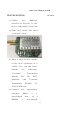
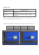
MOD190 TRANSCEIVER INSTALLATION 1) Solder antenna. the MOD190 transceiver directly to the host’s compatible connector. 2) Print and attach the label as shown below: 3) Place a label on the outside of the host enclosure in a visible area. On the label, include the following: “Contains Module Transmitter FCC MOD190” ID: and Transmitter P4U- “Contains Module IC: 4534A-MOD190” 4) Connect the antenna.
MOD190 TRANSCEIVER Application Requirements: applications. See Part 2.1091 for definitions of A) Power the MOD190 mobile Transceiver with 3.3VDC nominal peak voltage, current F) Do of not operate MOD190 750mA. without the an antenna. B) Do not remove the shield G) Documentations: on the MOD190. host’s C) If you use something other than fixed applications. with draw and the antenna or ¼ User the Manual include the following: wave the In a.
MOD190 TRANSCEIVER transmitter must be installed to provide a separation distance of at least 20cm from all person and not be colocated with any other transmitters except in accordance with FCC and Industry Canada multi-transmitter product procedures.” BEFORE APPLYING POWER! Check power and ground for proper polarity. Read the rest of this manual. TROUBLESHOOTING There are no user serviceable parts in the MOD190 Transceiver.
PARTS LIST PART NUMBER DESCRIPTION 021901A MOD190 RADIO TRANSCEIVER – WIRE ANTENNA 021902A MOD190 RADIO TRANSCEIVER – RPSMA ANTENNA There are no user-serviceable parts inside the transmitter or the receiver. Return the units for service. The information, specifications, and illustrations in this manual are those in effect at the time of printing. We reserve the right to change specifications or design at any time without notice. Part No. Antenna type Gain Remark 021901A WIRE ANTENNA 0.
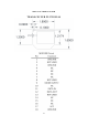
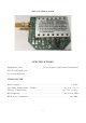
MOD190 TRANSCEIVER TRANSCEIVER PICTORIAL 8
MOD190 TRANSCEIVER SPECIFICATIONS Equipment Class ............................. Part 15 Spread Spectrum Transmitter FCC ID:P4U-MOD190 IC:4534A-MOD190 TRANSCEIVER Power supply ........................................................................... 3.3VDC Operating temperature - Radio....................................... -40˚C to +85˚C Storage temperature .................................................. -40˚C to +100˚C RF Frequency ................................................................
MOD190 TRANSCEIVER INSTRUCTION TO THE USER This device complies with Part 15 of the FCC rules. Operation is subject to the following two conditions: 1) this device may not cause harmful interference, and 2) this device must accept any interference received, including interference that may cause undesired operation. Note: This equipment has been tested and found to comply with the limits for a Class B digital device, pursuant to part 15 of the FCC Rules.
MOD190 TRANSCEIVER be co-located or operating in conjunction with any other antenna or transmitter. This modular must be installed and operated with a minimum distance of 20 cm between the radiator and user body. If the FCC identification number is not visible when the module is installed inside another device, then the outside of the device into which the module is installed must also display a label referring to the enclosed module.
MOD190 TRANSCEIVER INDUSTRY CANADA STATEMENTS This device complies with Industry Canada license-exempt RSS standard(s). Operation is subject to the following two conditions: (1) this device may not cause interference, and (2) this device must accept any interference, including interference that may cause undesired operation of the device. Le présent appareil est conforme aux CNR d'Industrie Canada applicables aux appareils radio exempts de licence.
MOD190 TRANSCEIVER OEM Responsibilities to comply with FCC and Industry Canada Regulations This device complies with Industry Canada’s licence-exempt RSSs. Operation is subject to the following two conditions: (1) This device may not cause interference; and (2) This device must accept any interference, including interference that may cause undesired operation of the device. Cet appareil est conforme aux CNR exemptes de licence d'Industrie Canada .
MOD190 TRANSCEIVER 1. This device complies with Industry Canada’s licence-exempt RSSs. Operation is subject to the following two conditions: (1) This device may not cause interference; and (2) This device must accept any interference, including interference that may cause undesired operation of the device. 2. Cet appareil est conforme aux CNR exemptes de licence d'Industrie Canada .