
Operating instructions


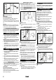
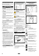
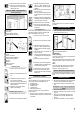
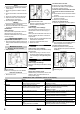
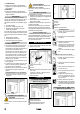
Table Of Contents
- Inhalt
- Allgemeine Hinweise
- Umweltschutz
- Zubehör und Ersatzteile
- Sicherheitshinweise
- Inbetriebnahme
- Bedienung
- Einstellungen
- Frostschutz
- Außerbetriebnahme
- Pflege und Wartung
- Transport
- Lagerung
- Hilfe bei Störungen
- Garantie
- Technische Daten
- EU-Konformitätserklärung
- Contents
- General notes
- Environmental protection
- Accessories and spare parts
- Safety instructions
- Initial startup
- Operation
- Settings
- Frost protection
- Shutting down
- Care and service
- Transport
- Storage
- Troubleshooting guide
- Warranty
- Technical data
- EU Declaration of Conformity
- Contenu
- Remarques générales
- Protection de l'environnement
- Accessoires et pièces de rechange
- Consignes de sécurité
- Mise en service
- Commande
- Réglages
- Protection antigel
- Mise hors service
- Entretien et maintenance
- Transport
- Stockage
- Dépannage en cas de défaut
- Garantie
- Caractéristiques techniques
- Déclaration de conformité UE
- Indice
- Avvertenze generali
- Tutela dell’ambiente
- Accessori e ricambi
- Avvertenze di sicurezza
- Messa in funzione
- Uso
- Impostazioni
- Antigelo
- Messa fuori servizio
- Cura e manutenzione
- Trasporto
- Stoccaggio
- Guida alla risoluzione dei guasti
- Garanzia
- Dati tecnici
- Dichiarazione di conformità UE
- Inhoud
- Algemene instructies
- Milieubescherming
- Toebehoren en reserveonderdelen
- Veiligheidsinstructies
- Inbedrijfstelling
- Bediening
- Instellingen
- Vorstbescherming
- Buitenwerkingstelling
- Onderhoud
- Vervoer
- Opslag
- Hulp bij storingen
- Garantie
- Technische gegevens
- EU-conformiteitsverklaring
- Índice de contenidos
- Avisos generales
- Protección del medioambiente
- Accesorios y recambios
- Instrucciones de seguridad
- Puesta en funcionamiento
- Manejo
- Ajustes
- Anticongelante
- Puesta fuera de servicio
- Cuidado y mantenimiento
- Transporte
- Almacenamiento
- Ayuda en caso de fallos
- Garantía
- Datos técnicos
- Declaración de conformidad UE
- Índice
- Indicações gerais
- Protecção do meio ambiente
- Acessórios e peças sobressalentes
- Avisos de segurança
- Arranque
- Operação
- Ajustes
- Protecção anticongelante
- Desactivação
- Conservação e manutenção
- Transporte
- Armazenamento
- Ajuda em caso de avarias
- Garantia
- Dados técnicos
- Declaração de conformidade UE
- Indhold
- Generelle henvisninger
- Miljøbeskyttelse
- Tilbehør og reservedele
- Sikkerhedshenvisninger
- Ibrugtagning
- Betjening
- Indstillinger
- Frostbeskyttelse
- Ud-af-brugtagning
- Pleje og vedligeholdelse
- Transport
- Opbevaring
- Hjælp ved fejl
- Garanti
- Tekniske data
- EU- overensstemmelseserklæring
- Indhold
- Generelle merknader
- Miljøvern
- Tilbehør og reservedeler
- Sikkerhetsanvisninger
- Igangsetting
- Betjening
- Innstillinger
- Frostbeskyttelse
- Ta ut av drift
- Stell og vedlikehold
- Transport
- Lagring
- Bistand ved feil
- Garanti
- Tekniske data
- EU-samsvarserklæring
- Innehåll
- Allmän information
- Miljöskydd
- Tillbehör och reservdelar
- Säkerhetsinformation
- Idrifttagning
- Manövrering
- Inställningar
- Frostskydd
- Urdrifttagning
- Skötsel och underhåll
- Transport
- Förvaring
- Hjälp vid störningar
- Garanti
- Tekniska data
- EU-försäkran om överensstämmelse
- Sisältö
- Yleisiä ohjeita
- Ympäristönsuojelu
- Lisävarusteet ja varaosat
- Turvaohjeet
- Käyttöönotto
- Käyttö
- Säädöt
- Pakkassuojaus
- Käytöstä poistaminen
- Hoito ja huolto
- Kuljetus
- Varastointi
- Ohjeet häiriötilanteissa
- Takuu
- Tekniset tiedot
- EU- vaatimustenmukaisuusvakuutus
- Περιεχόμενα
- Γενικές υποδείξεις
- Προστασία του περιβάλλοντος
- Παρελκόμενα και ανταλλακτικά
- Υποδείξεις ασφαλείας
- Έναρξη χρήσης
- Χειρισμός
- Ρυθμίσεις
- Αντιπαγετική προστασία
- Θέση εκτός λειτουργίας
- Φροντίδα και συντήρηση
- Μεταφορά
- Αποθήκευση
- Αντιμετώπιση βλαβών
- Εγγύηση
- Τεχνικά στοιχεία
- Δήλωση συμμόρφωσης EΕ
- İçindekiler
- Genel uyarılar
- Çevre koruma
- Aksesuarlar ve yedek parçalar
- Güvenlik bilgileri
- İşletime alma
- Kullanım
- Ayarlar
- Antifriz
- Kullanım dışına alma
- Bakım ve koruma
- Taşıma
- Depolama
- Arıza durumunda yardım
- Garanti
- Teknik bilgiler
- AB Uygunluk Beyanı
- Содержание
- Общие указания
- Защита окружающей среды
- Принадлежности и запасные части
- Указания по технике безопасности
- Ввод в эксплуатацию
- Управление
- настройки
- Защита от замерзания
- Вывод из эксплуатации
- Уход и техническое обслуживание
- Транспортировка
- Хранение
- Помощь при неисправностях
- Гарантия
- Технические характеристики
- Декларация о соответствии стандартам ЕС
- Tartalom
- Általános utasítások
- Környezetvédelem
- Tartozékok és pótalkatrészek
- Biztonsági utasítások
- Üzembe helyezés
- Kezelés
- Beállítások
- Fagyvédelem
- Üzemen kívül helyezés
- Ápolás és karbantartás
- Szállítás
- Tárolás
- Segítség üzemzavarok esetén
- Garancia
- Műszaki adatok
- EU-megfelelőségi nyilatkozat
- Obsah
- Obecné pokyny
- Ochrana životního prostředí
- Příslušenství a náhradní díly
- Bezpečnostní pokyny
- Uvedení do provozu
- Obsluha
- Nastavení
- Ochrana před mrazem
- Odstavení z provozu
- Péče a údržba
- Přeprava
- Skladování
- Nápověda při poruchách
- Záruka
- Technické údaje
- EU prohlášení o shodě
- Kazalo
- Splošni napotki
- Varovanje okolja
- Pribor in nadomestni deli
- Varnostna navodila
- Zagon
- Upravljanje
- Nastavitve
- Zaščita pred zamrzovanjem
- Ustavitev delovanja
- Nega in vzdrževanje
- Transport
- Skladiščenje
- Pomoč pri motnjah
- Garancija
- Tehnični podatki
- Izjava EU o skladnosti
- Spis treści
- Ogólne wskazówki
- Ochrona środowiska
- Akcesoria i części zamienne
- Zasady bezpieczeństwa
- Uruchamianie
- Obsługa
- Ustawienia
- Ochrona przeciwmrozowa
- Wyłączenie z eksploatacji
- Czyszczenie i konserwacja
- Transport
- Składowanie
- Usuwanie usterek
- Gwarancja
- Dane techniczne
- Deklaracja zgodności UE
- Cuprins
- Indicaţii generale
- Protecţia mediului
- Accesorii şi piese de schimb
- Indicaţii privind siguranţa
- Punerea în funcțiune
- Operarea
- Setări
- Protecţia împotriva îngheţului
- Scoaterea din funcțiune
- Îngrijirea şi întreţinerea
- Transport
- Depozitarea
- Remedierea defecţiunilor
- Garanţie
- Date tehnice
- Declaraţie de conformitate UE
- Obsah
- Všeobecné upozornenia
- Ochrana životného prostredia
- Príslušenstvo a náhradné diely
- Bezpečnostné pokyny
- Uvedenie do prevádzky
- Obsluha
- Nastavenia
- Ochrana proti mrazu
- Vyradenie z prevádzky
- Ošetrovanie a údržba
- Preprava
- Skladovanie
- Pomoc pri poruchách
- Záruka
- Technické údaje
- EÚ vyhlásenie o zhode
- Sadržaj
- Opće napomene
- Zaštita okoliša
- Pribor i zamjenski dijelovi
- Sigurnosni napuci
- Puštanje u pogon
- Rukovanje
- Postavke
- Zaštita od smrzavanja
- Stavljanje izvan pogona
- Njega i održavanje
- Transport
- Skladištenje
- Pomoć u slučaju smetnji
- Jamstvo
- Tehnički podaci
- EU izjava o sukladnosti
- Sadržaj
- Opšte napomene
- Zaštita životne sredine
- Pribor i rezervni delovi
- Sigurnosne napomene
- Puštanje u pogon
- Rukovanje
- Podešavanja
- Zaštita od mraza
- Stavljanje van pogona
- Nega i održavanje
- Transport
- Skladištenje
- Pomoć u slučaju smetnji
- Garancija
- Tehnički podaci
- EU izjava o usklađenosti
- Съдържание
- Общи указания
- Защита на околната среда
- Аксесоари и резервни части
- Указания за безопасност
- Пускане в експлоатация
- Обслужване
- Настройки
- Защита от замръзване
- Спиране от експлоатация
- Грижа и поддръжка
- Транспортиране
- Съхранение
- Помощ при повреди
- Гаранция
- Технически данни
- Декларация за съответствие на ЕС
- Sisukord
- Üldised juhised
- Keskkonnakaitse
- Lisavarustus ja varuosad
- Ohutusjuhised
- Käikuvõtmine
- Käsitsemine
- Seaded
- Külmakaitse
- Käigustvõtmine
- Hooldus ja jooksevremont
- Transport
- Ladustamine
- Abi rikete korral
- Garantii
- Tehnilised andmed
- EL vastavusdeklaratsioon
- Saturs
- Vispārīgas norādes
- Vides aizsardzība
- Piederumi un rezerves daļas
- Drošības norādījumi
- Ekspluatācijas uzsākšana
- Apkalpošana
- Iestatījumi
- Pretaizsalšanas aizsardzība
- Ekspluatācijas pārtraukšana
- Kopšana un apkope
- Transportēšana
- Uzglabāšana
- Palīdzība traucējumu gadījumā
- Garantija
- Tehniskie dati
- ES atbilstības deklarācija
- Turinys
- Bendrosios nuorodos
- Aplinkos apsauga
- Priedai ir atsarginės dalys
- Saugos nurodymai
- Eksploatavimo pradžia
- Valdymas
- Nustatymai
- Apsauga nuo šalčio
- Eksploatavimo pabaiga
- Techninė priežiūra ir eksploatacinės parengties užtikrinimas
- Transportavimas
- Laikymas
- Trikčių šalinimas
- Garantija
- Techniniai duomenys
- ES atitikties deklaracija
- Зміст
- Загальні вказівки
- Охорона довкілля
- Приладдя та запасні деталі
- Вказівки з техніки безпеки
- Введення в експлуатацію
- Керування
- Налаштування
- Захист від морозу
- Виведення з експлуатації
- Догляд та технічне обслуговування
- Транспортування
- Зберігання
- Допомога в разі несправностей
- Гарантія
- Технічні характеристики
- Декларація про відповідність стандартам ЄС

8 English
Care and service
Daily
1. Empty the coin cassette (see "Mainte-
nance tasks").
2. Check the general condition of the de-
vice.
3. Check the condition of the valve connec-
tor.
4. Check the condition of the hose lines.
5. Open the lower cover and check the
condition of the compressor.
6. Have damaged parts replaced.
Weekly
1. Clean the outside of the device.
2. Drain the condensate in the compressed
air tank (see "Maintenance tasks").
ATTENTION
Risk of damage
The water in the compressed air line can
damage the tyre pressure sensor.
Drain the condensate in the compressed
air tank regularly.
Service very 2 years
Only with AWT -C, AWT -C Fp
1. Have the pressure measuring device of
the tyre inflator calibrated by the gauging
office.
Maintenance work
Emptying the coin cassette
1. Open the door.
1 Door
2 Coin cassette
2. Remove and empty the coin cassette.
Drain the condensate
1. Remove the cover.
1 Bar cover
2 Condensate drain valve
2. Hold the condensate drain valve over a
shaft or collecting container.
몇 WARNING
Risk of injury, risk of damage
The water stream escaping from the con-
densate drain valve can cause injury or
damage.
Never point the condensate drain valve at
people, animals, the device or electrical
components.
3. Slowly open the condensate drain valve
and drain the condensate.
4. Close the condensate drain valve.
5. Attach the cover.
Transport
몇 CAUTION
Risk of injury, risk of damage
Be aware of the weight of the device during
transportation.
1. When transporting in vehicles, secure
the device against slipping and tipping
over according to the applicable guide-
lines.
Storage
몇 CAUTION
Risk of injury and damage
Be aware of the weight of the device during
storage.
Troubleshooting guide
DANGER
Danger from electric shock.
Before working on the device, set the main
switch to “OFF” and disconnect the on-
board power supply.
The device does not work
Check the on-site voltage supply.
Set the main switch to "ON" position.
Contact customer service.
The device does not start after the valve
connector has been connected to the
tyre.
Check that the valve connector is seated
correctly.
Check the condition of the hose and of
the valve connector.
Press the “tyre flat” button.
There is no compressed air
Pull the compressor on-button upward.
1 Compressor on-button
The compressor is overheated: Wait un-
til the compressor has cooled off.
The tyre pressure is too low
Check the pressure on the pressure
gauge. Readjust the pressure reducer if
necessary.
1 Pressure reducer
2 Pressure gauge
Malfunctions with information shown on the display
Fault Cause Rectification
ER1 Unstable pressure measurement due to
defective valve connector or hose
Replace the valve connector.
Replace the hose.
ER2, ER7 The tyre pressure is too low.
Unstable pressure measurement due to
defective valve connector or hose.
Check the tyre pressure on the pressure gauge and re-
adjust the pressure reducer if necessary.
Replace the valve connector.
Replace the hose.
ER3 The tyre pressure is too low. Check the pressure on the pressure gauge and read-
just the pressure reducer if necessary.
ER4 The tyre pressure is too high. Check the pressure on the pressure gauge and read-
just the pressure reducer if necessary.
ER5 The voltage supply is disturbed. Contact customer service.
ER6, ER8, ER9, ERU, ERB Malfunction in the electronics. Contact customer service.
ERP The valve connector came loose during in-
flation.
The tyre pressure is not stable.
Check that the valve connector is seated correctly.
Check the pressure on the pressure gauge and read-
just the pressure reducer if necessary.