
User Manual
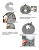


STEP FIVE
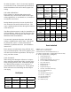
Rest the oat on the base plate of the unit. Connect
the oat to the base plate using the 3/8” x 1” bolt (Part
#B13) and 3/8” lock washer (Part #B14). Tighten us-
ing a 9/16” wrench.
STEP SIX
Center the Top Screen (Part #B7) inside the three Top
Float Brackets. Attach the screen by spanning each
Top Screen Clip (Part #B8) across the two innermost
rings on the screen and the hole in the oat bracket.
Insert the 3/4” Brass Screws (Part #B9) and attach
with 1/4” Lock Washers (Part #B10) and 1/4” Nuts
(Part #B11) to secure the screen to the oat assembly.
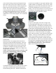
STEP SEVEN
Take at mesh pattern and wrap into cone shape by
overlapping both vertical edges by approximately
1 inch and aligning top and bottom edges of mesh.
Secure mesh vertical seam at the top, bottom and
middle using (3) cable ties.
5.1JF, 5.3JF, 7.3JF
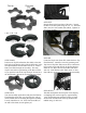
STEP THREE
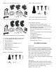
Position one Top Float Bracket (Part #B2) so that the
bolt holes in the bracket align with the bolt holes in the
two adjoined oat sections and insert two 9” Coated
Bolts (Part #B4) through the assembly. This may
require some minor repositioning of the oat sections
as you push the bolt all the way through. Do not force
the bolt through. Repeat for the remaining two joints.
STEP FOUR
Turn the assembly upside down and place the Bottom
Float Brackets (Part #B3) over the bolts, the ends of
which should now be extending through the assembly.
Loosely install the six 3/8” Lock Nuts (Part #B5) on
the ends of the bolts (do not tighten yet).