
User Manual
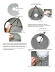
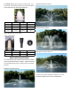


over the cone assembly (it may require light taps with
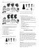
a rubber mallet to seat properly). Next, use the 3 Self
Tapping Screws (Part #D1) provided in the 3 holes on
the nozzle and tighten the screws into the cone as-
sembly. Once you feel resistance, two more turns will
be sufcient. To install the Spruce nozzle, follow the
same steps, but do not install the Y Insert.
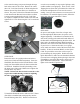
STEP NINE
On power cord lengths of 100 feet or longer with
the watertight Quick Disconnect, the power cord is
shipped separately. It should now be attached to the
stub cord by lining up the male and female halves of
the disconnect and hand tightening the blue collar. On
these cords, the Additional Strain Relief should be
attached to one of the lower oat brackets as pictured.
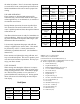
If you receive a 3 chain strain relief (6 or 8 gauge
cord), attach one chain to each of the three lower oat
brackets. If there is not Strain Relief, use the Nylon
Cable Tie provided to secure the cord to a rope to
prevent damage by the propeller. Double check the
Quick Disconnect to make sure the threaded collar has
not come loose in shipping before placing in the water.
If installing a new Quick Disconnect, please refer to
Quick Disconnect instructions. Also, at this time,
lights can be installed if purchased.
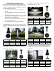
1 chain strain relief
Bottom Float Bracket
Chain
3 chain strain relief
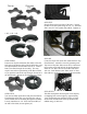
so the motor housing (can) passes through the large
hole in the center of the screen. Remove the center
three 3/8” Lock Nuts from the 9” Bolts and place the
Bottom Screen Clips (Part #B12) over the bolts as
shown. The power cord can be slid under the bottom
screen between the oat and screen where two oat
sections come together before the 3/8” Lock Nuts
are replaced. Replace the three inside Lock Nuts and
tighten all 3/8” Lock Nuts using the 9/16” wrench and
socket.
STEP EIGHT
Return the unit to its upright position and select a
nozzle (See Nozzle and Pattern Options). Insert the
Shaft Bolt (Part #D2) into the Nozzle Head so it ts
snugly into the molded socket for those nozzles that
use the bolt. Install the Nozzle by threading it into
the inner cone of the pump. Make sure to tighten the
Nozzle all the way down.
NOTE: If the nozzle does not look centered, see the
steps in the troubleshooting section for adjusting
the inner cone that the nozzle screws into.
To install the Redwood nozzle, make sure the Y Insert
(Part #D4) is installed and seated properly into the
Nozzle Housing (Part #D7). Push the nozzle down