
Cut Sheet


DESCRIPTION
The SIVFR is used to isolate, amplify, and condition DC voltage and current signals
from any source (power supplies, motors, tachometer generators, transducers, and
potentiometers). It also provides isolated inputs to control motor direction and an
isolated power supply for transducer or potentiometer operation. All input connections
are isolated from the AC line and motor wiring. The SIVFR installs easily onto the side of
the drive with the mounting base and two screws (provided). An adapter bracket is
provided for use with 1/2 HP model drives. The SIVFR is supplied with a finger-safe
panel, which may be used with the enclosure cover to close the unused exposed area
of the SIVFR between Terminal Blocks TB1 and TB2.
The main features of the SIVFR include voltage (0 – 5 VDC), current (4 – 20 mA
DC), or a potentiometer (5 kΩ) signal inputs and a Run/Fault Relay, which can be used
to turn on or off equipment or signal a warning if a fault occurs. The SIVFR has jumper
selectable features for signal input type (VOLT, CUR), relay operation (RUN, FAULT), relay
output contacts (NO, NC), and for use with or without the drive's optional dynamic
brake module (DBM, NDBM).
Other features of the SIVFR include a power on LED, barrier terminal blocks to
facilitate signal input and Run/Fault Relay wiring, and multi-turn trimpots (MAX1,
OFFSET) to readjust the SIVFR for use with 0 – 2.5 thru 0 – 25 VDC signal input volt-
ages for specific applications.
Optional features of the SIVFR are a second and third isolated signal input (with a
barrier terminal block and MAX2 and MAX3 adjustment trimpots for SIG2 and SIG3) and
an analog signal output (with a barrier terminal block for V out).
STANDARD FEATURES
• Multi-Turn trimpots for MIN & MAX Speed Adjustments.
• Accepts a wide range of Voltage Input Signals.
• Jumper Selection for Voltage or Current Input Signal.
• Barrier Terminal Block Facilitates Wiring.
• Protective Cover for Added Safety. • Power On LED. • Run/Fault Relay.
OPTIONAL FEATURES
• Second and third isolated signal inputs. (Part No. 9588).
• Analog signal output. (Part No. 9589).
Signal Isolator
Provides isolation between
non-isolated signal sources and the Drive.
Run/Fault Relay
Used to turn on or off equipment or
signal a warning if a fault occurs.
SIVFR
SIGNAL ISOLATOR with RUN/FAULT RELAY
For all KBVF Models
DATA SHEET D-805
COPYRIGHT © 2008 KB Electronics, Inc.
Description Specification
Factory
Setting
Voltage Following Input Range at SIG1
(MAX1 Trimpot) (Volts DC)
0 – ±2.5 thru 0 – ±25 0 – 5
Current Following Input Range at SIG1
(OFFSET Trimpot) (mA DC)
4 – 20 —
Potentiometer Operation (kΩ)5—
FWD and REV Input Switch Types
Dry Contact or
Open Collector
—
+5V and -5V Power Supply Maximum Load
Current Rating (mA DC)
5
Run/Fault Relay Output Contacts Ratings
(Amps at 30 Volts DC, 125 Volts AC)
1, 0.5 —
Input/Output Linearity (%) 0.5 —
Thermal Drift (mV / ºC) 1.0 —
Operating Temperature Range (ºC / ºF) 0 – 45 / 0 – 113 —
GENERAL PERFORMANCE SPECIFICATIONS
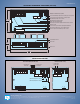
Unidirectional Main Speed Potentiometer and
Forward-Stop-Reverse Switch Connections
(J1 Installed in “VOLT” Position)
Run/Fault Relay
Connection
Main Speed
Potentiometer
(5k)
Reverse
Stop
Forward
Low
High
Wiper
+5V 0V-5V FWD SIG1REV COM1
TB1
VOLTCUR
J1
Output Contacts
Run/Fault Relay
TB2
K1 K2
Bidirectional Voltage Following
Signal Input Connection
(J1 Installed in “VOLT Position)
Unidirectional (Forward) Current
Following Signal Input Connection
(J1 Installed in “CUR” Position)
SIG1REV0V FWD+5V -5V COM1
Volts DC
0 to ±2.5 thru 0 to ±25
TB1
Jumper Jumper
VOLTCUR
J1
SIG1REV0V FWD+5V -5V COM1
4 - 20 mA DC
TB1
Jumper
J1
CUR VOLT
Form “C” Contact or Relay
Forward-Stop-Reverse Connection
Open Connector
Forward-Stop-Reverse Connection
TB1
FWD+5V -5V 0V COM1REV SIG1
Forward Reverse
-5V+5V 0V REVFWD SIG1 COM1
TB1
ReverseForward
SIVFR (Part No. 9597)