
Cut Sheet


(A42098) – Rev. C – 5/2008
Print Code
KB ELECTRONICS, INC.
12095 NW 39th Street, Coral Springs, FL 33065-2516 • (954) 346-4900 • FAX (954) 346-3377
Outside Florida Call Toll Free (800) 221-6570 • info@kbelectronics.com
www.kbelectronics.com
COPYRIGHT © 2008 KB Electronics, Inc.
DATA SHEET D-805
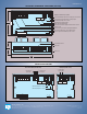
J2: Sets the Run/Fault Relay Output Contacts for normally open or closed opera tion.
All jumpers are shown in factory set positions.
TB2: Run/Fault Relay Output Contacts connection.
J4: Sets the operation of the Run/Fault Relay to "Run" or "Fault".
CON1: Used for the Ribbon Cable to connect the SIVFR to the Drive.
MAX1: Maximum Speed adjustment trimpot.
OFFSET: Signal Offset adjustment trimpot.
TB1: Main Speed Potentiometer, Signal Input, and Direction Switch connections.
J1: Sets the drive for operation with a voltage or current input signal.
J5: Sets the drive for operation with the optional Dynamic Brake Module.
PWR: Power on LED.
8-segment Finger-Safe Panel.
Enclosure cover.
Enclosure base.
32.0
1.26
4.05
103
FAULT
J4
RUN
J5
DBMNDBM
CON1
61.5
2.42
+5V -5V OV REVFWD SIG1 COM1
PWR TB1
OFFSET MAX1
K1
TB2
K2
CUR VOLT
J1
NONC
J2
J5
NDBM DBM
CON1
FAULT
J4
RUN
OV+5V -5V SIG1FWD REV COM1
PWR TB1
MAX1OFFSET
MAX2 MAX3
K1 K2 J2J1
VOLTCUR
NC NO
TB2
MAX3 Trimpot: Adjustment for SIG3 Input
MAX2 Trimpot: Adjustment for SIG2 Input
COM2
0 to 2.5 thru 0 to 25
TB3
SIG2
0 to 2.5 thru 0 to 25
-
SIG3
V
+
Volts DC Input Volts DC Input
V
+
-
SIG2 and SIG3 Option (Part No. 9588) Vout Option (Part No. 9589)
VOUTCOM3
(±5% at 5 mA DC)
+
-
0 - 3 Volts DC Output
FAULT
J4
RUN
MAX1OFFSET
K1 K2 J2J1
VOLTCUR
NC NO
TB2
SIVFR LAYOUT and MECHANICAL SPECIFICATIONS (Inches/mm)
FACTORY INSTALLED OPTIONS