
Datasheet

SMU INSTRUMENTS
www.keithley.com
1.888.KEITHLEY
(U.S. only)
A Greater Measure of Confidence
SPECIFICATION CONDITIONS
This document contains specifications and supplemental information for the Models 2601B,
2602B, and 2604B System SourceMeter
®
SMU instruments. Specifications are the standards against
which the Models 2601B, 2602B, and 2604B are tested. Upon leaving the factory, the 2601B,
2602B, and 2604B meet these specifications. Supplemental and typical values are non- warranted,
apply at 23°C, and are provided solely as useful information.
Accuracy specifications are applicable for both normal and high capacitance modes.
The source and measurement accuracies are specified at the SourceMeter CHANNEL A (2601B,
2602B, and 2604B) or SourceMeter CHANNEL B (2602B and 2604B) terminals under the following
conditions:
1. 23°C ± 5°C, <70% relative humidity
2. After 2 hour warm-up
3. Speed normal (1 NPLC)
4. A/D auto-zero enabled
5. Remote sense operation or properly zeroed local operation
6. Calibration period = 1 year
SOURCE SPECIFICATIONS
VOLTAGE SOURCE SPECIFICATIONS
VOLTAGE PROGRAMMING ACCURACY
1
Range
Programming
Resolution
Accuracy (1 Year)
23°C ±5°C
±(% rdg. + volts)
Typical Noise
(peak-peak)
0.1Hz–10Hz
100 mV 5 µV 0.02% + 250 µV 20 µV
1 V 50 µV 0.02% + 400 µV 50 µV
6 V 50 µV 0.02% + 1.8 mV 100 µV
40 V 500 µV 0.02% + 12 mV 500 µV
TEMPERATURE COEFFICIENT (0°–18°C and 28°–50°C)
2
: ±(0.15 × accuracy specification)/°C.
Applicable for normal mode only. Not applicable for high capacitance mode.
MAXIMUM OUTPUT POWER AND SOURCE/SINK LIMITS
3
: 40.4W per channel maximum.
±40.4V @ ±1.0A, ±6.06V @ ±3.0A, four quadrant source or sink operation.
VOLTAGE REGULATION: Line: 0.01% of range. Load: ±(0.01% of range + 100µV).
NOISE 10Hz–20MHz: <20mV peak-peak (typical), <3mV RMS (typical), 6V range.
CURRENT LIMIT/COMPLIANCE
4
: Bipolar current limit (compliance) set with single value.
Minimum value is 10nA. Accuracy same as current source.
OV ERSHOOT: <±(0.1% + 10mV) typical. Step size = 10% to 90% of range, resistive load,
maximum current limit/compliance.
GUARD OFFSET VOLTAGE: <4mV typical. Current <10mA.
CURRENT SOURCE SPECIFICATIONS
CURRENT PROGRAMMING ACCURACY
Range
Programming
Resolution
Accuracy (1 Year)
23°C ±5°C
±(% rdg. + amps)
Typical Noise
(peak-peak)
0.1Hz–10Hz
100 nA 2 pA 0.06% + 100 pA 5 pA
1 µA 20 pA 0.03% + 800 pA 25 pA
10 µA 200 pA 0.03% + 5 nA 60 pA
100 µA 2 nA 0.03% + 60 nA 3 nA
1 mA 20 nA 0.03% + 300 nA 6 nA
10 mA 200 nA 0.03% + 6 µA 200 nA
100 mA 2 µA 0.03% + 30 µA 600 nA
1 A
5
20 µA 0.05% + 1.8 mA 70 µA
3 A
5
20 µA 0.06% + 4 mA 150 µA
10 A
5, 6
200 µA 0.5 % + 40 mA (typical)
TEMPERATURE COEFFICIENT (0°–18°C and 28°–50°C)
7
: ±(0.15 × accuracy specification)/°C.
MAXIMUM OUTPUT POWER AND SOURCE/SINK LIMITS
8
: 40.4W per channel maximum.
±1.01A @ ±40.0V , ±3.03A @ ±6.0V , four quadrant source or sink operation.
CURRENT REGULATION: Line: 0.01% of range. Load: ±(0.01% of range + 100pA).
VOLTAGE LIMIT/COMPLIANCE
9
: Bipolar voltage limit (compliance) set with a single value.
Minimum value is 10mV. Accuracy is the same as voltage source.
OV ERSHOOT: <±0.1% typical (step size = 10% to 90% of range, resistive load; see Current Source
Output Settling Time for additional test conditions).
ADDITIONAL SOURCE SPECIFICATIONS
TRANSIENT RESPONSE TIME: <70µs for the output to recover to within 0.1% for a 10% to 90%
step change in load.
VOLTAGE SOURCE OUTPUT SETTLING TIME: Time required to reach within 0.1% of final value
after source level command is processed on a fixed range.
100mV, 1V Ranges: <50µs typical.
6V Range: <100µs typical.
40V Range
10
: <150µs typical.
CURRENT SOURCE OUTPUT SETTLING TIME: Time required to reach within 0.1% of final value
after source level command is processed on a fixed range. Values below for I
out
× R
load
= 1V
unless noted.
3A Range: <80µs typical (current less than 2.5A, R
load
>2W).
1A–10mA Ranges: <80µs typical (R
load
>6W).
1mA Range: <100µs typical.
100µA Range: <150µs typical.
10µA Range: <500µs typical.
1µA Range: <2.5ms typical.
100nA Range: <25ms typical.
DC FLOATING VOLTAGE: Output can be floated up to ±250VDC from chassis ground.
REMOTE SENSE OPERATING RANGE
11
:
Maximum voltage between HI and SENSE HI = 3V .
Maximum voltage between LO and SENSE LO = 3V .
VOLTAGE OUTPUT HEADROOM:
40V Range: Max. output voltage = 42V – total voltage drop across source leads (maximum 1W
per source lead).
6V Range: Max. output voltage = 8V – total voltage drop across source leads (maximum 1W per
source lead).
OVER TEMPERATURE PROTECTION: Internally sensed temperature overload puts unit in
standby mode.
VOLTAGE SOURCE RANGE CHANGE OVERSHOOT: <300mV + 0.1% of larger range (typical).
Overshoot into an 100kW load, 20MHz BW.
CURRENT SOURCE RANGE CHANGE OVERSHOOT: <5% of larger range + 300mV/R
load
(typical
with source settling set to SETTLE_SMOOTH_100NA). See Current Source Output Settling Time
for additional test conditions.
NOTES
1. Add 50µV to source accuracy specifications per volt of HI lead drop.
2. High Capacitance Mode accuracy is applicable at 23°C ±5°C only.
3. Full power source operation regardless of load to 30°C ambient. Above 30°C and/or power sink operation,
refer to “Operating Boundaries” in the Series 2600B Reference Manual for additional power derating
information.
4. For sink mode operation (quadrants II and IV), add 0.06% of limit range to the corresponding current limit
accuracy specifications. Specifications apply with sink mode operation enabled.
5. Full power source operation regardless of load to 30°C ambient. Above 30°C and/or power sink operation,
refer to “Operating Boundaries” in the Series 2600B Reference Manual for additional power derating
information.
6. 10A range accessible only in pulse mode.
7. High Capacitance Mode accuracy is applicable at 23°C ±5°C only.
8. Full power source operation regardless of load to 30°C ambient. Above 30°C and/or power sink operation,
refer to “Operating Boundaries” in the Series 2600B Reference Manual for additional power derating
information.
9. For sink mode operation (quadrants II and IV), add 10% of compliance range and ±0.02% of limit setting to
corresponding voltage source specification. For 100mV range add an additional 60mV of uncertainty.
10. Add 150µs when measuring on the 1A range.
11. Add 50µV to source accuracy specifications per volt of HI lead drop.
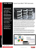
Series 2600B
System SourceMeter
®
SMU Instruments
Series 2600B specifications
Series 2600B specifications