
Datasheet

SMU INSTRUMENTS
www.keithley.com
1.888.KEITHLEY
(U.S. only)
A Greater Measure of Confidence
METER SPECIFICATIONS
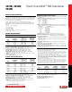
VOLTAGE MEASUREMENT ACCURACY
17, 18
Range
Default Display
Resolution
19
Input
Resistance
Accuracy (1 Year)
23°C ±5°C
±(% rdg. + volts)
200 mV 100 nV >10 GW 0.015% + 225 µV
2 V 1 µV >10 GW 0.02% + 350 µV
20 V 10 µV >10 GW 0.015% + 5 mV
200 V 100 µV >10 GW 0.015% + 50 mV
TEMPERATURE COEFFICIENT (0°–18°C and 28°–50°C)
20
: ±(0.15 × accuracy specification)/°C.
Applicable for normal mode only. Not applicable for high capacitance mode.
CURRENT MEASUREMENT ACCURACY
18, 21
Range
Default Display
Resolution
22
Voltage
Burden
23
Accuracy (1 Year)
23°C ±5°C
±(% rdg. + amps)
100 nA 100 fA <1 mV 0.06% + 100 pA
1 µA 1 pA <1 mV 0.025% + 500 pA
10 µA 10 pA <1 mV 0.025% + 1.5 nA
100 µA 100 pA <1 mV 0.02% + 25 nA
1 mA 1 nA <1 mV 0.02% + 200 nA
10 mA 10 nA <1 mV 0.02% + 2.5 µA
100 mA 100 nA <1 mV 0.02% + 20 µA
1 A 1 µA <1 mV 0.03% + 1.5 mA
1.5 A 1 µA <1 mV 0.05% + 3.5 mA
10 A
24
10 µA <1 mV 0.4% + 25 mA (typical)
CURRENT MEASURE SETTLING TIME (Time for measurement to settle after a Vstep)
25
: Time
required to reach 0.1% of final value after source level command is processed on a fixed range.
Values for V
out
= 2V unless noted. Current Range: 1mA. Settling Time: <100µs (typical).
TEMPERATURE COEFFICIENT (0°–18°C and 28°–50°C)
26
: ±(0.15 × accuracy specfication)/°C.
Applicable for normal mode only. Not applicable for high capacitance mode.
CONTACT CHECK
27
(not available on Model 2614B)
Speed
Maximum Measurement
Time to Memory
For 60Hz (50Hz)
Accuracy (1 Year)
23°C ±5°C
±(%rdg. + ohms)
FAST 1 (1.2) ms 5% + 10 W
MEDIUM 4 (5) ms 5% + 1 W
SLOW 36 (42) ms 5% + 0.3 W
ADDITIONAL METER SPECIFICATIONS
MAXIMUM LOAD IMPEDANCE:
Normal Mode: 10nF (typical). High Capacitance Mode: 50µF (typical).
COMMON MODE VOLTAGE: 250VDC.
COMMON MODE ISOLATION: >1GW, <4500pF.
OVERRANGE: 101% of source range, 102% of measure range.
MAXIMUM SENSE LEAD RESISTANCE: 1kW for rated accuracy.
SENSE INPUT IMPEDANCE: >10GW.
SOURCE SPECIFICATIONS (continued)
PULSE SPECIFICATIONS (continued)
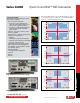
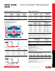
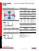
QUADRANT DIAGRAM:
+1.5A
+10A
–10A
–1A
+1A
+0.1A
–0.1A
–1.5A
+200V+5V
–5V
+20V–20V 0V
0A
+180V–180V–200V
DC
Pulse
Pulse
Pulse
2
2
2
2
4
4
1
3
3
3
3
NOTES
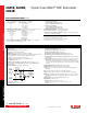
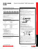
12. Times measured from the start of pulse to the start off-time; see figure below.
Pulse Level
Bias Level
Start t
on
Start t
off
90%
10%
t
on
t
off
10
%
13. Thermally limited in sink mode (quadrants II and IV) and ambient temperatures above 30°C.
See power equations in the reference manual for more information.
14. Voltage source operation with 1.5 A current limit.
15. Typical performance for minimum settled pulse widths:
Source Value Load
Source Settling
(% of range) Min. Pulse Width
5 V 0.5 W 1% 300 µs
20 V 200 W 0.2% 200 µs
180 V 180 W 0.2% 5 ms
200 V (1.5 A Limit) 200 W 0.2% 1.5 ms
100 mA 200 W 1% 200 µs
1 A 200 W 1% 500 µs
1 A 180 W 0.2% 5 ms
10 A 0.5 W 0.5% 300 µs
Typical tests were performed using remote operation, 4W sense, and best, fixed measurement range. For more
information on pulse scripts, see the Series 2600B Reference Manual.
16. Times measured from the start of pulse to the start off-time; see figure below.
Pulse Level
Bias Level
Start t
on
Start t
off
90%
10%
t
on
t
off
10
%
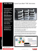
2611B, 2612B,
2614B
System SourceMeter
®
SMU Instruments
Series 2600B specifications
Series 2600B specifications