
Installation Guide


10
Application Notes & Charging Charts (Cooling Mode Only)
• This equipment’s cooling system contains refrigerant under high pressure. Always use safe and
environmentally sound methods when handling refrigerant handling or servicing the unit. Review the
factory literature and safety warnings prior to servicing.
• Whenrepairingsystemleaks,alwaysuseanitrogen(inert)gastoprotecttherefrigerantsystemandpressure
check the repair before re-charging. Always replace the filter-dryers when performing any repair to the refrigeration
system with one capable of acid removal. After completing the repairs, evacuate the system to 350 - 500 microns
and weigh in the refrigerant to the amount specified on the unit rating label.
• Chargingchartsarevalidforavarietyofindoor,returnairconditionsandaremostinuencedbytheoutdoor
ambient temperature, outdoor fan operation and the unit operating voltage. Before using these charts, make sure
the unit is in a stable operating mode. As shown in the charging charts: Figure 6, Figure 7 (page 11), Figure
8 (page 11), Figure 9 (page 12), Figure 10 (page 12), Figure 11 (page 13), & Figure 12 (page 13),
the ideal system sub-cooling can vary over the range of operation. Reference the charts to determine the ideal
amount of sub-cooling for a given liquid pressure. Units charged to other values will not perform at the rated unit
efficiency (EER) or rated Coefficient of Performance (COP) in heating mode.
• Toinspectasystemsoperationusingqualityinstruments,matchthemeasuredliquidtemperaturetotheunits
chart. The measured liquid pressure reading should be within 3% of the charts value for most installations.
• Forsystemsthatareoperatingwithmorethana5%deviation,inspecttheunitforthepropervoltageandphase
balance and the refrigeration system for leaks.
• Unitsthatareoperatingatlessthen95%ofthenominalvoltageorwitha2%phaseimbalancemayseeamore
significant deviation than the amount stated above.
• DO NOT use the charts in systems that have a fan cycling under low-ambient control. Refer to the low-ambient
kit instructions for more information. (If applicable)
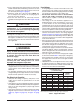
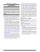
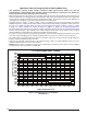
Figure 6. Charging Chart for 1.5 Ton Models
(TXVMatches)
200
220
240
260
280
300
320
340
360
380
400
420
440
460
480
500
520
540
560
580
600
75 80 85 90 95 100 105110 115 120 125130 135
1 1/2 Ton Charging Chart - Cooling
Liquid Temperature (
0
F)
Liquid Pressure (psig)
Remove refrigerant when above the curve
Add refrigerant when below the curve