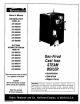
® Owner'sManual CONTINUOUS PILOT MODEL NO. 229.960330 229.960340 229.960360 229.960360 229.960370 229.960380 229.960390 ELECTRONIC INTERMITTENT IGNITION MODEL NO. 220.960230 229.960240 229.960260 229.960260 229.960270 229.960280 229.960290 Theseinstructionsmustbe affixed onor adjacentto the boiler. CAUTION Readall instructionscarefully beforestartingtheinstallation.
Warranty .................................................... Rules for Safe Installation and Operation .................. Boiler Ratings and Capacities ............................. Before You Start ............................................ Locating the Boiler ......................................... Fresh Air for Combustion .................................. Installation - System Piping ............ : ................... Chimney and Vent Pipe Connection ....................... Vent Damper Operation ..
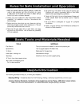
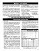
1. Read the Owner's Manual carefully Failure to fallow the rules for safe operation and the instructions can cause a malfunction of the boiler and result in death, serious bodily injury, and/or property damage. 2. Check your local codes and utility requirements before installation, The installation must be in accordance with their directives, 3. Before servicing, allow boiler to cool. Always shut off any electricity and gas to boiler when working on it. This will prevent any electrical shocks or burns. 5.
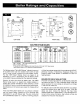
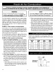
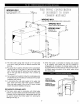
VENT DAMPER ASME POP SAFETY PRESSURE GAUGE LIMIT RESSURE261/=" ONTROL 43/,= . VALVE ,; J i / J 2'/2" NPT \ : 29" ; \ _ : I SWITCI-€ I WATER LiNE -- ", : I SPILL iL __ -'_ PROBE ROLLOUT 36_e" _$8 -SWITCH _ -, _o _ 6 CUT'OFF 24" GAS _ GAS A .... _ UNE ; FRONT LEFT SIDE DESIGN CERTIFIED FOR NATURAL GAS RIGHT SIDE I i GAS-FIRED STEAM BOILERS "[h_TURALG/_ BOILER MODEL NUMBER INTERMrr_NT IGNITION Wr_l VIg_IT I_MPER 229960230 22996024O 229960250 229960260 229.
Checkto besureyouhavetherightsizeboilerbeforestartingtheinstallation. See rating and capacitytable on previouspage. Also be sure the new boiler is for the type of gas you are using. Checkthe ratingplate on the rightsideof theboiler. You must see that the boiler is suppliedwith the correct type of gas, fresh air for combustion,and a suitableelectricalsupply Also,the boiler mustbe connectedto a suitablechimneyand an adequatepiping system.
Provision for combustion and ventilation air must be in accordance with Section 5.3, Air for Combustionand Ventilation, of the National Fuel Gas Code, ANSI Z223.1-1atest revision, or applicable provisions of the local building codes. WARNING NOTE Be sure to provide enough fresh air for combustion. Enoughair insuresproper combustionand assures that no hazardwilldevelopdue to the lackof oxygen. If you use a fireplace or a kitchen or bathroom exhaust fan, you should install an outside air intake.
The near boiler piping, that is the piping around the boiler, must be considered as part of the boiler for proper water level control, and to produce dry steam. Correct near boiler piping is crucial to the proper operation of the boiler and the heating system. Follow these recommendations carefully 1 Place boiler in selected possible. location, as near chimney or on discharge pipes between such safety valves and the atmosphere.
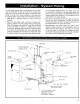
5. For installers choosing to use both supply tappings, Figure 6A shows the correct way to pipe this system. Figure 6B shows the wrong way to pipe a header with two risers. • Headers must be fitted with header offsets or swing joints, or be equipped with expansion joints, so that thermal expansion and contraction of the header will not damage the boiler. Headers shall not be welded. • System takeoffs from the header must be between the equalizer and the riser to the header nearest the equalizer.
WRONG WAY DO NOT BULLHEAD,USE TWO TAKEOFFS THIS PIPING CONFIGURATION IS INCORRECTTO SHOW COMMONMISTANES WRONG WAY TAKE OFFS MUST BE BETWEEN RISER & EQUALIZER WRONG WAY SWING JOINTS ARE MISSING )NG WAY MISSING TEE FOR SKIMMING 12. The near boiler piping shall include a 1V2" ball valve in the return piping as shown for bottom blowdown and draining. 13.
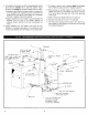
I In accordance with Part 7, VenUng of Equipment, of the National Fuel Gas Code, For boilers for connection gas vents or provisions chimneys, vent shall be ANSI Z223.1-1atest revision to and applicable of theinstallations local building codes. CHECK YOUR CHIMNEY 7. Run pipe as directly as possible with as few elbows as possible. This is a very important part of your heating system. It must be clean, the right size, properly constructed and in GOOD CONDITION.
4 Placein operation theappliancebeinginspected.Follow the lightinginstructions. Adjustthermostat so appliance willoperatecontinuousl_z 5. Testfor spillageatthe drafthoodreliefopeningafter5 minutes ofmainburneroperation. Usetheflameofa match or candle,or smokefroma cigarette, cigaror pipe 6.
For safe, efficient operation, the vent damper and all flue product carrying areas of the appliance must be checked annually by you, with particular attention given to deterioration from corrosion or other sources. If you see corrosion or other deterioration, contact your heating contractor for repairs. Check vent damper operation as follows: thermostat will control the burner firing as before, while the damper will remain open. DO NOT turn damper open manually or motor damage will result.
NATURAL GAS Pipe Capactty- BTU Per Hourlnput Includes Fittings Length of Pipe - Ft. ½" ¾" 1" MANUAL SHUT-OFF 1%" 20 92,000 190,000 350,000 625,000 40 63,000 130,000 245,000 445,000 60 50,000 ! 05,000 195,000 365,000 VALVE AUTOMATIC VALVE GROUND JOINT MANIFOLD UNION S OI.ENTTRAP FLOOR LINE ELECTRIC POWER SUPPLY All electrical work must conform to local codes, as well as the National Electrical Code, ANSI/NFPA-70, latest revision.
probetypelowwatercutotis,thismayoccureachtimethe lowwatercutoffdetectsa lowwaterconditionIf thisis the case,an isolationrelayis requiredforthethermostat circuit A24voltsinglepolesinglethrow(SPST) normally open(N.O.) relay _s required,such as the HoneywellR8222Aor equivalent. Wireasshownin Fig.14Aor Fig.14B. VENT DAMPER 4 VENT DAMPER PLN MOLEX PLUG The boiler is equipped with a factory wired harness with 4 pin molex plug, that plugs into the 4 pin molex receptacle inside the vent damper operator.
EFFIKAL MOLEX I 15V/BOHZ/I f L_ pOWER SUPPLY B_X r -l_ RVGP PLUG VENT OA,_PER ) _ \/ j\®/ ..... L_ INTERMITTENT IGNITION iiii _____.j'--" OP_ONAL WF-2U-2_. WATi_ _"l{EOER NOTE: T_¼1N_. N0 ] APpFJ_R$ ONLy ON WATER FEEC_R MODELS WITH tJXNL_I. _£0 PUSH 8U_'ON.
STANDING PILOT EFFIKAL MOLEX HeVI_OHZll m RVGP PLUG i( pOW_ SUpPLy V_NT DAMPER )@( Y 8K .T PRESSURE UMIT _ _SO3NNECT A r ...... ', IQ-÷ ....... J I I I I_@-4 L_X=/___J- _--WIRE ..... NUT COLOR CODE 8X-B_ BR-E_ROWN 0 -ORANGE y -YELLOW R -RED BT-B_ VCh'H TRACER W -WHITE G -GREEN 8 -BLUE RVGP-KS-BKF OPI1ONAL _-2U--:14 W_TER REED_ NOTE: TERMIteS. NO, 3 APpF_S C_NLY ON WATER F_ER MOC_'LS MANUAL BEF.,D PUSH t_,rrTON VENT OA._PER OOUBL_ I POLE, DOUBLE RELAy /-; II I 12_.
INTERMITTENT EFFIKAL 24 RVGP MOLEX VENT PLUG IGNITION DAMPER VOLT TRANSFORMER 115V/BOHZ/I_ POWER % SUPPLY .oT-_Jo-. _ 0V£RCURRENT PROTECTED DISCONNECT W NEUT pR_SSURC \ LIMIT ) \(_ ..... OPTIONAL WF-2U-24 WAFER FEEDER I_-- WIRE NOTE: TERMINAL NO. 3 APPEARS ONLY ON WATER FEEDER MODELS WITH MANUAL FEED PUSH NUT RVCp-KS-BKF FLAME ROLLOUI T BUTTON GAS VALVE V,ENT O_IpzR I 7 _ _6 i I I is i ...... " °," Kt oD _ Ir ZNr DAtaPER C_.81E -- ,' r -- r r.
EFFIKAL RVGP VENT DAMPER MOLEX PLUG STANDING PILOT 24 VOLT TRANSFORMER IIBV/6OHZ/I¢ POWER SUPPLY HOT ._----_--_ OVERCURRENT PROTECTED DISCONNECT W NEUT PRESSURE BT I I J LIMIT y LOW WATER CUT OFF OPTIONAL WF-2U-24 WATER FEEDER _ NOTE: VALVE TERMINAL NO. 3 APPEARS ONLY ON WATER FEEDER MODELS WITH MANUAL FEED PUSH BUTTON. BK B TR T_ I_ -- WIRE K TH NUT FLAME ROLLOUT SAFETY SHUTOFF RVCp-KS-BKF V_NT BLOCKED VENT SAFETY SHUTOFF OA._pER TO OC.
POP SAFETY VALVE The pop safety valve should open automatically if the boiler steam pressure exceeds the pressure rating of the valve (15 psig). Should it ever fail to open under this condition, shut down your boiler. If valve discharge occurs, or valve fails to open as described above, contact an authorized contractor or qualified service technician to replace the pop safety valve and inspect the heating system to determine the cause, as this may indicate an equipment malfunction.
WARNING: If you do not follow these instructions exactly, a fire or explosion may result causing property damage, personal injury or loss of life. A. Some boilers are equipped with an intermittent ignition device which automatically lights the pilot. Do not try to light the pilot by hand. • Immediately call your gas supplier from a neighbor's phone. Follow the gas supplier's instructions. • If you cannot reach your gas supplier, call the fire department.
1. STOP! Readthesafetyinformation onpage16. 2. Setthethermostat to lowestsetting. 3. Turnoffallelectricpowertotheappliance. 4. Removelowerfrontpanel. 5. Rotategas controlknob slightlyand turn clockwise to GAS CONTROL KNOB [-SHOWN / 9 Rotate the gas control knob counterclockwise _, to "PILOT" Push down and hold the red reset button while you light pilot burner with a match. After about one minute, re[ease reset button.
HOW A STEAM SYSTEM OPERATES THERMOSTAT The water in the boiler is heated until it reaches the boiling point. As the water boils it turns into steam. The steam rises from the top of the water through the supply main to the radiation units. As it passes through the radiators it releases its heat and condenses into water. The water returns to the Keep it set at a desired room temperature. If windows are to be opened or heat is not needed, move thermostat pointer to a lower setting.
ADJUST PILOT BURNER differential adjustment at 1 psi, i.e. the steam pressure required in the radiators. This will give us a cut-off setpoint of 11/2psi. Pilot flame should surround 3/8' to 1/2" of the pilot sensor. Refer to Fig. 19. If flame needs adjusting, do it as follows: The above is an example of a typical one pipe system.
drop the pressure setting until the boiler shuts down. This will show that the pressure limit is operating properly Refer to control manufacturer's more information. instructions (enclosed} for 3/8" to 1/2" Check thermostat operation. When set above temperature indicated on the thermometer, boiler should ignite. Make certain the thermostat turns off the boiler when room temperature reaches the selected setting and starts the boiler operating when room temperature falls a few degrees.
CLEANING YOUR BOILER FLUE PASSAGES Check thewater levelevery dayortwo.Verifythewater lineshown by operating thedrainvalveonthegauge. BESURE TOPANDBOTTOM AND BURNERS VALVES ONGAUGE ARE ALWAYS OPEN SOTHAT ACTUAL WATER LEVEL FluePassagesbetweensectionsshouldbe examinedyearlyandcleaned, WILL BESHOWN ATALLTIMES, if necessaryTo clean,removeburners,pilot, and venl pipe,Removetop Thegauge glass should bedryabove thewater line. Thewater lineshould and front jacketpanels.
You may avoid inconvenience and service calls by checking these points before you call for service. FOR YOUR SAFETY WHAT TO DO IF YOU SMELL GAS 1. Do Not try to light any appliance. 2. Do not touch any electric switch, do not use the phone. 3. Leave the building immediately, then call your gas supplier. 4. If you cannot reach the gas supplier, call the fire department. Possible Cause What to do Thermostat is not set correctly Reset thermostat above room temperature.
GAS-FIRED STEAM BOILERS -- IMPORTANT -READ THESE INSTRUCTIONS BEFORE ORDERING 18 15\ All parts listed in the following Parts List may be ordered through your nearest supplier. When ordering parts, first obtain the Model Number from the data plate on your boiler, then determine the Part No. (not the Key No.} and the Description of each part from the following illustrations and list. Be sure to give us all this information: 16. . _ 19 20 The Part No, - The Part Description - The Boiler Model No.
FOR USE WITH NATURAL GAS ONLY 6 4 5 NOTE: Actual gas valve may look different than gas valve shown GAS BURNERS AND MANIFOLD PARTS THIS iS A REPAIR PARTS LIST - NOT A PACKING LIST II KEY NO. 1 2 3 4 5 6 6A 7 DESCRIPTION 24 Volt GasValve,Elect.Inter.Ignition PilotTube 10-32x 1/2 HexHeadScrew GasManifold MainBurnerOrifice" MainBurner,Regular*" MainBurner,PilotMount Pilot Burner Air Shutter Air ShutterSpring 1 3 7 24Volt GasValve,ContinuousPilot 3 SECTION Pad No.
BOILER CONTROLS AND PIPING 12 KEY NO.
ElectronicIgnition ® Owner'sManual Gas-Fired Cast Iron STEAM BOILER CONTINUOUS PILOT MODELNO. 229.960330 229.960340 229.960350 229.960360 229.960370 229.960380 229.960390 ELECTRONIC INTERMITTENT IGNITION MODEL NO. 229.960230 229.960240 Now that you ever exist for Sears Service when you call have purchased your Boiler, should a need repair parts or service, simply contact any Center. Be sure to provide all pertinent facts or visit.