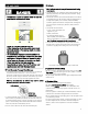
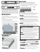
Use & Care Guide Manual de Uso y Cuidado English / Español Kenmore Liquid Propane Gas Grill ® Parrilla a gas de propano líquido Model/Modelo: PG-40405S0L P/N 40500500 ®
DANGER If you smell gas: 1. Shut off gas to the appliance. 2. Extinguish any open flame. 3. Open lid. 4. If odor continues, keep away from the appliance and immediately call your gas supplier or your fire department WARNING 1. Do not store or use gasoline or other flammable liquids or vapors in the vicinity of this or any other appliance. 2. An LP cylinder not connected for use shall not be stored in the vicinity of this or any other appliance.
TABLE OF CONTENTS WARNING For Your Safety . . . ....2 Grill Service Center. . . ....2 Product Record Information . . . ....2 Installation Safety Precautions . . . ....2 Safety Symbols . . . ....2 Kenmore Grill Warranty . . . ....4 Use and Care . . . . . 5-11 Parts List . . . . . . 12 Parts Diagram . . . . . . 13 Before Assembly . . . . 14-17 Assembly . . . . 18-29 Troubleshooting . . . .
WARRANTY KENMORE GRILL WARRANTY KENMORE LIMITED WARRANTY WITH PROOF OF SALE, the following warranty coverage applies when this appliance is correctly installed, operated and maintained according to all supplied instructions. FOR ONE YEAR from the date of sale this appliance is warranted against defects in material or workmanship. A defective appliance will receive free repair. If the appliance cannot be repaired it will be replaced free of charge.
USE AND CARE DANGER • NEVER store a spare LP cylinder under or near the appliance or in an enclosed area. • Never fill a cylinder beyond 80% full. • If the information in the two points above is not followed exactly, a fire causing death or serious injury may occur. • An overfilled or improperly stored cylinder is a hazard due to possible gas release from the safety relief valve. This could cause an intense fire with risk of property damage, serious injury or death.
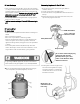
LP Tank Exchange Connecting Regulator To The LP Tank • Many retailers that sell grills offer you the option of replacing your empty LP tank through an exchange service. Use only those reputable exchange companies that inspect, precision fill, test and certify their cylinders. Exchange your tank only for an OPD safety feature-equipped tank as described in the "LP Tank" section of this manual. • Always keep new and exchanged LP tanks in upright position during use, transit or storage.
Leak Testing Valves, Hose and Regulator 1. Turn all grill control knobs to OFF. 2. Be sure regulator is tightly connected to LP tank. Hold coupling nut and regulator as shown for proper connection to LP tank valve. 3. Completely open LP tank valve by turning OPD hand wheel counterclockwise. If you hear a rushing sound, turn gas off immediately. There is a major leak at the connection. Correct before proceeding by calling Permasteel for replacement parts at 1-888-287-0735, M – F 8:00 – 5:00 PACIFI 4 .
WARNING For Safe Use of Your Grill and to Avoid Serious Injury: • Do not let children operate or play near grill. • Keep grill area clear and free from materials that burn. • Do not block holes in sides or back of grill. • Use grill only in well-ventilated space. NEVER use in enclosed space such as carport, garage, porch, covered patio, or under an overhead structure of any kind. • Do not use charcoal or ceramic briquettes in a gas grill. • Use grill at least 3 ft. from any wall or surface. Maintain 10 ft.
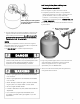
WARNING Turn controls and gas source or tank OFF when not in use. Burner Flame Check • Remove cooking grates and heat diffusers. Light burners, turn knobs from HI to LO. You should see a smaller flame in LO position than seen on HI. Perform burner flame check on searing burner, also. Always check flame prior to each use. If only low flame is seen refer to "Sudden flame drop or low flame" in the Troubleshooting Section.
• Stainless steel surfaces: To maintain your grill’s high quality appearance, wash with mild detergent and warm soapy water and wipe dry with a soft cloth after each use. Baked-on grease deposits may require the use of an abrasive plastic cleaning pad. Use only in direction of brushed finish to avoid damage. Do not use abrasive pad on areas with graphics.
Food Safety B A Food safety is a very important part of enjoying the outdoor cooking experience. To keep food safe from harmful bacteria, follow these four basic steps: Clean: Wash hands, utensils, and surfaces with hot soapy water before and after handling raw meat and poultry. Separate: Separate raw meats and poultry from ready-to-eat foods to avoid cross contamination. Use a clean platter and utensils when removing cooked foods. Cook: Cook meat and poultry thoroughly to kill bacteria.
Key Description Qty Part Number Key 1 2 3 4 5 6 7 8 9 10 11 12 13 14 15 16 17 18 19 20 21 22 23 24 25 26 27 28 29 30 31 32 33 34 35 36 37 Side Burner Lid Rotate Rod, Side Burner Lid Side Burner Grid Searing Burner Double Ignition Wire Searing Burner Base Drip Box Right Side Shelf Electronic ignition module Igniter Cover Fascia, Right Side Shelf Control Panel Gas Valve, Main Burner Igniter Wire Main Burner Tube Searing Valve Side Burner Manifold Side Burner Hose Ground wire Control Knob Bezel Control K
PARTS DIAGRAM 13
BEFORE ASSEMBLY NOTICE: Once you have unpacked the grill according to the STOP SHEET instructions, check all grill parts against the pictures on this and the following two pages. If you parts are missing or damaged, call 1-888-287-0735.
BEFORE ASSEMBLY 15
BEFORE ASSEMBLY 16
ASSEMBLY CAREFULLY READ AND PERFORM ALL ASSEMBLY INSTRUCTIONS ON THE FOLLOWING PAGES. Tools Required: Adjustable wrench (not provided) Screwdriver (not provided) 7/16” Combination wrench (not provided) The following hardware is provided in blister pack for convenient use.
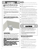
1 2 Bottom Shelf □ Turn bottom shelf upside down. Attach the front panel to bottom shelf with (8) M4x10 screws. □ Attach the casters to bottom shelf with (16) M6x13 screws. Note: Install each caster into the correct position as shown in the figure below. The standard caster (non-swiveling) will only install in one direction. □ Turn bottom shelf right side up, lock caster brakes to stabilize unit for further assembly. Attach door magnet box to bottom shelf with (2) M4x10 screws.
Cart □ To attach side panels, align side panel holes with screw insert holes on each side of bottom shelf. Note: Left side panel has match holder attachment. □ Attach but do not fully tighten left and right side panels to bottom shelf with (6) M6x13 screws. Leave a small gap beneath the screw heads for easier attachment of panels, brackets and bars in the following steps on this page. (A) □ Attach back panel to bottom shelf and two side panels with (8) M4x10 screws .
Electronic Ignition Module □ Attach electronic ignition module through mounting hole on right side panel. See A □ Insert rubber gasket followed with plastic lock nut and tighten by hand.
Front Doors □ Attach left and right grease tray brackets to side panels with (8) M4X10 screws. See A □ Remove the (4) M5x15 screws pre-assembled to the door handle, and use them to attach handles to doors. See B □ Insert the pin at the bottom of each door into the hole on the bottom panel. Insert the pin at the top of each door through the hole in the door bracket hinge. See C IMPORTANT: If the doors do not line up when closed or do not close freely, the hinges may need to be adjusted.
Grill Head to Cart □ This step requires two people to lift and position grill head onto cart. □ If not already done, remove the tie wrap and packing material from regulator hose, burner valve and igniter wires located under control panel. Separate the 2 searing burner wires (straight connection tip) from the other 7 wires (right-angle connection tip) shown in step 6.
Burner Electrode and Igniter Cover □ Place the 5 burner electrode wires (thin black & thin orange), the ground wire (red capped) and the igniter wire (large black) through the pre-installed side panel clamp. See A. Note: If wires are difficult to install, loosen the clamp screw, put the wires through the clamp and retighten the screw. □ Place the 4 thin black wires and 1 thin orange wire into the 5 narrow slots in the electronic ignition module.
Left Side Shelf □ Attach fascia to left side shelf with (2) M5x10 hex bolts and (2)M5 flat washers and (1) M4X10 hex bolt . (A-B) □ Hang left side shelf onto two pre-installed screws on left side of firebox. (C) □ Attach shelf to firebox as follows: - From inside to outside of firebox with (3) M6x13 screws and (3) M6 flat washers. (D) IMPORTANT: Make sure side shelf fascia is aligned with control panel before tightening screws. - From outside to inside of firebox with (1) M4x12 screw.
Right Side Shelf □ Attach fascia to right side shelf with (2) M5x10 hex bolts and (2)M5 flat washers and (1) M4X10 hex bolt with the supplied wrench. (A-B) □ Hang right side shelf onto two pre-installed screws on right side of firebox. (C) □ Attach shelf to firebox as follows: - From inside to outside of firebox with (3) M6x13 screws and (3) M6 flat washers. (D) IMPORTANT: Make sure side shelf fascia is aligned with control panel before tightening screws.
Searing Burner Remove plastic packaging from searing burner valve. Remove searing burner grate from searing burner shelf. Attach ignition wire to side burner valve. (A )Remove the 2 pre-installed screws from the valve control stem and set them aside. (B) Loosen the searing burner to insert gas valve. First loosen and remove the screw attaching the electrode to the shelf and set the screw aside. (C) Then loosen and remove the 2 screws holding searing burner in place.
G H G H I J K L M N P Q 27
Heat Diffusers, Cooking Grates and Warming Rack □ Place heat diffusers over burners. Diffusers will fit in firebox in either direction. □ Place cooking grates onto grate rests at front and rear of firebox. □ Insert warming rack into brackets at top of firebox as shown.
13 Drip Tray, Drip cup and LP tank □ Insert the drip tray into bottom of firebox from back. Then open the door and insert the drip cup into the drip cup slot. □ Feed the regulator and hose through the hole in the right side panel. □ LP tank is sold separately. Use only with an OPD (Overfill Protection Device) equipped LP tank. Fill and leak check before attaching to grill and regulator. □ Place LP tank into hole in bottom shelf with tank collar opening facing to the front as shown.
EMERGENCIES: If a gas leak cannot be stopped, or a fire occurs due to gas leakage, call the fire department. Problem Gas leaking from cracked/cut/burned hose. Possible Cause • Damaged hose. Gas leaking from LP cylinder. • Mechanical failure due to rusting or mishandling. Gas leaking from LP cylinder valve. • Failure of cylinder valve from mishandling or mechanical failure. Gas leaking between LP • Improper installation, connection not cylinder and regulator tight, failure of rubber seal. connection.
Troubleshooting (continued) Problem Possible Cause Burner(s) will not light using igniter. (See Electronic Ignition Troubleshooting also) ELECTRONIC IGNITION: • No spark, no ignition noise. Pro • Sparks, but not at electrode or at full strength. Burner(s) will not match light. • See “GAS ISSUES:” on previous page. • Match will not reach. • Improper method of match-lighting. Sudden drop in gas flow or low flame. • Out of gas. Prevention/Solution Prevention/Solution • No spark, some ignition noise.
Troubleshooting - Electronic Ignition Problem Possible Cause Check Item Prevention/Solution SECTION I No sparks appear at any electrodes when control knob turned to HI: no noise can be heard from spark module. • Battery not installed properly. • Dead battery. • Button assembly not installed properly. • Faulty spark module. • Check battery orientation. • Has battery been used previously? • Check to insure threads are properly engaged. Button should travel up and down without binding.
PELIGRO Si siente olor a gas: 1. Cierre el paso de gas al aparato. 2. Apague toda llama al descubierto. 3. Abra la tapa. 4. Si persiste el olor, aléjese del aparato y llame inmediatamente al proveedor local de gas o a los bomberos. ADVERTENCIA 1. No guarde ni use gasolina ni otros líquidos o gases inflamables cerca de éste ni de cualquier otro aparato. 2. No guarde un tanque de gas propano, que no esté conectado, cerca de éste ni de cualquier otro aparato.
ÍNDICE DE MATERIAS Por su propia seguridad . . . . . 33 Centro de servicio para parrillas.. . . . . 33 Información de inscripción de la garantía . . . . 33 Símbolos de seguridad. . . . . 33 Medidas de seguridad para la instalación . . . . . 33 Garantía para la parrilla Kenmore . . . Uso y mantenimiento . . . Lista de piezas . . . Vista esquemática de las piezas . . . Armado . . . . 35 . . . 36-42 . . . 43 . . 44 . . . 45-48 Antes De La Asamblea . . . . 49-60 Resolución de problemas . . . .
GARANTÍA GARANTÍA DE LA PARRILLA KENMORE GARANTÍA LIMITADA DE KENMORE CON LA PRUEBA DE VENTA, la siguiente cobertura de garantía se aplica cuando este electrodoméstico se instala, opera y mantiene correctamente de acuerdo con todas las instrucciones provistas. POR UN AÑO a partir de la fecha de venta, este electrodoméstico está garantizado contra defectos de material o mano de obra. Un electrodoméstico defectuoso recibirá reparación gratuita. Si el artefacto no puede repararse, será reemplazado sin cargo.
UOS Y MANTENIMIENTO • NUNCA guarde un cilindro de gas de repuesto debajo o cerca del aparato o en un areacerrada. • Nunca llene un cilindro más allá del 80% completo. • Si la información en los dos puntos anteriores no se siguen exactamente, un incendio causando la muerte o pueden producir lesiones graves. • Un cilindro de un llenado excesivo o mal almacenado es un peligro debido a la liberación de gas posible de la válvula de seguridad.
Cambio del tanque de gas • Muchos comerciantes minoristas que venden parrillas, le ofrecen la opción de cambiar su tanque de gas vacío mediante un servicio de recambio. Emplee únicamente empresas de recambio de buena reputación, que inspeccionen, carguen con precisión, verifiquen y certifiquen sus cilindros. Cambie su tanque sólo por otros tanques equipados con el dispositivo de seguridad volumétrica que se describe en la sección de Tanques de gas de este manual.
Prueba para detectar fugas de las válvulas, las mangueras y el regulador Sostenga la tuerca de unión y el regulador, como se ilustra, para conectarlos bien a la válvula del tanque. 6. Gire la tuerca de unión en el sentido de las agujas del reloj, apretándola hasta que no se mueva más. El regulador formará un sello en el dispositivo de seguridad de la válvula del tanque, lo que creará cierta resistencia.
ADVERTENCIA Para usar su parrilla en forma segura y para evitar lesiones graves: • No permita que los niños operen o jueguen cerca de la parrilla. • Mantenga el área de la parrilla despejada y libre de materiales que se quemen. • No bloquee los agujeros en los lados o la parte posterior de la parrilla. • Use la parrilla solo en espacios bien ventilados. NUNCA lo use en espacios cerrados tales como garaje, garaje, porche, patio cubierto o debajo de una estructura aérea de ningún tipo.
ADVERTENCIA Gire los controles y la fuente de gas o el tanque a la posición OFF cuando no esté en uso. Comprobación de llama del quemador • Retire las parrillas de cocción y los difusores de calor. Encienda los quemadores, gire las perillas de HI a LO. Debería ver una llama más pequeña en la posición LO que se ve en HI. Realice la verificación de la llama del quemador en el quemador abrasador, también. Siempre revise la llama antes de cada uso.
• Piezas plásticas: Lávelas con agua jabonosa tibia y séquelascon un paño • Superficies de porcelana: Debido a su composición vítrea, la mayoría de los residuos se puede eliminar con un paño empapado en una solución de bicarbonato de soda y agua, o con un limpiador especialmente formulado. Use un polvo limpiador no abrasivo para las manchas difíciles de eliminar. • Superficies pintadas: Lávelas con un detergente suave o un limpiador no abrasivo y agua tibia jabonosa. Séquelas con un paño suave, no abrasivo.
Seguridad alimentaria B A Cocina indirecta Las aves de corral y los grandes cortes de carne se cocinan lentamente a la perfección en la parrilla por calor indirecto. Coloque los alimentos sobre los quemadores sin encender; el calor de los quemadores iluminados circula suavemente por toda la parrilla, cocinando carne o aves sin tocar una llama directa.
LISTA DE PARTES Key Description Qty Part Number Key Qty Part Number 1 1 41500041 38 1 40500211 3 Tapa del quemador lateral Rote la vara, la tapa del quemador lateral Rejilla del quemador lateral Cesta Bar ángulo de ayuda 2 40500074 39 Tirador 2 40500082 1 50600203 40 puerta derecha 1 40500080 4 Abrasador del quemador 1 40900142 41 puerta izquierda 1 40500076 5 Alambre de doble encendido 1 50600225 42 Panel lateral izquierdo 1 40500061 6 Devastación de la hornilla
S DIAGRAM 44
ANTES DEL MONTAJE AVISO: Una vez que usted haya desempaquetado la parrilla según las instrucciones de la HOJA de la PARADA, compruebe todas las piezas de la parrilla contra los cuadros en esto y las dos páginas siguientes. Si usted parte es que falta o dañado, la llamada 1-888-287-0735.
ANTES DEL MONTAJE 46•
ANTES DEL MONTAJE 47
ASAMBLE LEA Y REALICE CUIDADOSAMENTE TODAS LAS INSTRUCCIONES DE ASAMBLEA EN LAS PÁGINAS SIGUIENTES. Las herramientas requirieron: El destornillador de la llave ajustable no proporcionada no proporcionado 7/16” la llave combinada (no proporcionada) el hardware siguiente se proporciona en el paquete de ampolla para el uso conveniente.
1 2 Estante inferior □ Girar estante inferior al revés. Coloque el panel frontal al estante inferior con (8) tornillos M4x10. □ Una las ruedas a la plataforma inferior con (16) tornillos M6x13. Nota: Instale cada echador en la posición correcta según las indicaciones de la figura abajo. El echador estándar (el no-girar sobre un eje) instalará solamente en una dirección.
Carro □ Para unir paneles laterales, alinee los agujeros de la pierna del panel lateral con los agujeros de la pierna en cada lado del estante inferior. Nota: Panel lateral izquierdo tiene apego portafósforos. □ Adjuntar pero no apriete completamente los paneles laterales izquierdo y derecho de la repisa inferior con (6) tornillos M6x13. Deje un pequeño espacio debajo de las cabezas de los tornillos para facilitar la unión de paneles, soportes y bares en los siguientes pasos de esta página.
Módulo de encendido electrónico □ Fije el módulo de encendido electrónico a través del orificio de montaje en el panel lateral derecho.(A) □ Junta de goma Insertar siguió con la tuerca de seguridad de plástico y apriete con la mano.
Puertas delanteras Fije los soportes de la bandeja de grasa izquierdo y derecho a los paneles laterales con (8) tornillos M4x10. A. Quite los tornillos (4) M5x15 premontados a los extremos de la manija de la puerta, y utilícelos para unir las manijas a las puertas. B. Inserte el pasador en la parte inferior de cada puerta en el agujero en el panel inferior.Inserte el pasador en la parte superior de cada puerta por el agujero de la bisagra soporte de la puerta. C.
Cabeza de la parrilla al carro □ Este paso requiere a dos personas levantar y colocar la cabeza de la parrilla sobre el carro. □ Si no lo ha hecho, retire la banda de sujeción y el material de embalaje de la manguera del regulador, válvula del quemador y los cables de ignición situados debajo del panel de control. Separar los 2 cables del quemador ardientes de los otros 7 hilos que se muestran en el paso 6.
Quemador de electrodos y la cubierta del encendedor □ Coloque los 5 electrodos del electrodo del quemador (negro fino y naranja fino), el cable de tierra (con tapa roja) y el cable del encendedor (negro grande) a través de la abrazadera del panel lateral preinstalada. A. Nota: Si los cables son difíciles de instalar, afloje el tornillo de sujeción, ponga los cables a través de la abrazadera y vuelva a apretar el tornillo.
Estante del lado izquierdo 9 Adjuntar la fascia de la repisa del lado izquierdo con (2) tornillos hexagonales M5x10 y (2) arandelas planas M5 y (1) perno hexagonal M4X10. (A-B) Cuelgue la repisa lateral izquierda en dos tornillos preinstalados en el lado izquierdo de la caja de fuego. Fije la repisa de la siguiente manera firefox: (C) - Desde adentro fuera de la caja de fuego con (3) tornillos M6x13 y (3) arandelas planas M6.
Estante del derecho Adjuntar la fascia de la repisa del lado derecho con (2) tornillos hexagonales M5x10 y (2) arandelas planas M5 y (1) perno hexagonal M4X10. (A-B) Cuelgue la repisa del lado derecho en dos tornillos preinstalados en el lado derecho de la caja de fuego.(C) Fije la repisa de la siguiente manera firefox: - Desde adentro fuera de la caja de fuego con (3) tornillos M6x13 y (3)arandelas planas M6.
Hornilla que se chamusca Retirar los envases de plástico de la válvula del quemador abrasador. Retire la rejilla del quemador abrasador de la repisa del quemador abrasador. Fije el cable de encendido a la válvula del quemador lateral. (A) Retire los 2 tornillos preinstalados desde el vástago de control de la válvula y la puso a un lado.(B) Aflojar el quemador abrasador para insertar la válvula de gas.
G G H I J K L M N P 58 H Q
Rejillas y difusores de calor, cocina estante que se calienta □ Coloque difusores de calor sobre los quemadores. Difusores caben en la cámara de combustión en cualquier dirección. □ Coloque las parrillas de cocción sobre sus rejilla descansa en la parte delantera y trasera de la cámara de combustión. □ Inserte la rejilla para calentar en los soportes en la parte superior de la cámara de combustión como se muestra .
13 Gotee la bandeja, la taza del goteo y el tanque del LP □ Inserte la bandeja de goteo en la parte inferior de la caja de fuego desde la parte posterior. A continuación, abra la puerta e inserte la cubeta de escurrido en la ranura de la taza de goteo. □ Alimentar el regulador y la manguera a través del agujero en el panel lateral derecho. □ LP tanque de gas se vende por separado. Use sólo con una (Dispositivo de protección contra sobrellenado) OPD tanque de gas equipada.
EMERGENCIAS: Si no se puede detener una fuga de gas, o si ocurre un incendio debido a una fuga de gas, llame a los bomberos. Causas probables Problema Fuga de gas de mangueras quebradas, cortadas o quemadas. • Manguera dañada. Medidas de prevención / solución • Cierre el gas en el cilindro o en la fuente de los sistemas de gas natural. Si tiene todo tipo de desperfectos, pero no está quemada, cambie la válvula/la manguera/ el regulador.
Resolucion de problemas (continuacion) Problema El quemador o los quemadores no se enciende(n) al usar el encendedor. Pro Causas probables • El cable o el electrodo está cubierto con restos de comida. • Los cables están flojos o desconectados. • Los cables producen cortocircuitos (chispas) entre el encendedor y el electrodo. BOTÓN PULSADOR PIEZOELÉCTRICO Y GIRATORIO: • El botón pulsador se pega en el fondo. • La perilla giratoria gira sin hacer clic. • Hay chispas entre el encendedor y el electrodo.
Resolución de problemas – Encendido electrónico Problema (encendido) Causas probables Procedimiento de revisión Medidas de prevención / solución SECCIÓN I • La pila no está • Revise la orientación de la pila. • Instale la pila (verifique que los polos “+” y No aparecen chispas en instalada • ¿Es una pila usada? “–” estén orientados correctamente, con el ningún electrodo cuando se adecuadamente.