DANGER If you smell gas: 1. Shut off gas to the appliance. 2. Extinguish any open flame. 3. Open lid. 4. If odor continues, keep away from the appliance and immediately call your gas supplier or your fire department WARNING 1. Do not store or use gasoline or other flammable liquids or vapors in the vicinity of this or any other appliance. 2. An LP cylinder not connected for use shall not be stored in the vicinity of this or any other appliance.
TABLE OF CONTENTS WARNING For Your Safety . . . ....2 Grill Service Center. . . ....2 Product Record Information . . . ....2 Installation Safety Precautions . . . ....2 Safety Symbols . . . ....2 Kenmore Grill Warranty . . . ....4 Use and Care . . . . . 5-11 Parts List . . . . . . 12 Parts Diagram . . . . . . 13 Before Assembly . . . . 14-17 Assembly . . . . 18-28 Troubleshooting . . . .
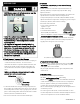
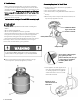
LP Cylinder USE AND CARE DANGER • NEVER store a spare LP cylinder under or near the appliance or in an enclosed area. • Never fill a cylinder beyond 80% full. • If the information in the two points above is not followed exactly, a fire causing death or serious injury may occur. • An overfilled or improperly stored cylinder is a hazard due to possible gas release from the safety relief valve. This could cause an intense fire with risk of property damage, serious injury or death.
LP Tank Exchange • Many retailers that sell grills offer you the option of replacing your empty LP tank through an exchange service. Use only those reputable exchange companies that inspect, precision fill, test and certify their cylinders. Exchange your tank only for an OPD safety feature-equipped tank as described in the "LP Tank" section of this manual. • Always keep new and exchanged LP tanks in upright position during use, transit or storage.
Leak Testing Valves, Hose and Regulator 1. Turn all grill control knobs to OFF. 2. Be sure regulator is tightly connected to LP tank. Hold coupling nut and regulator as shown for proper connection to LP tank valve . 3. Completely open LP tank valve by turning OPD hand wheel counterclockwise. If you hear a rushing sound, turn gas off immediately. There is a major leak at the connection. Correct before proceeding by calling Sears for replacement parts at 1-844-553-6667. 4 .
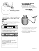
WARNING For Safe Use of Your Grill and to Avoid Serious Injury: • Do not let children operate or play near grill. • Keep grill area clear and free from materials that burn. • Do not block holes in sides or back of grill. • Use grill only in well-ventilated space. NEVER use in enclosed space such as carport, garage, porch, covered patio, or under an overhead structure of any kind. • Do not use charcoal or ceramic briquets in a gas grill. • Use grill at least 3 ft. from any wall or surface. Maintain 10 ft.
WARNING Turn controls and gas source or tank OFF when not in use. Burner Flame Check • Remove cooking grates and heat diffusers. Light burners, turn knobs from HI to LO. You should see a smaller flame in LO position than seen on HI. Perform burner flame check on searing burner, also. Always check flame prior to each use. If only low flame is seen refer to "Sudden flame drop or low flame" in the Troubleshooting Section.
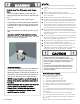
• Painted surfaces: Wash with mild detergent or nonabrasive cleaner and warm soapy water. Wipe dry with a soft nonabrasive cloth. • Stainless steel surfaces: To maintain your grill’s high quality appearance, wash with mild detergent and warm soapy water and wipe dry with a soft cloth after each use. Baked-on drip deposits may require the use of an abrasive plastic cleaning pad. Use only in direction of brushed finish to avoid damage. Do not use abrasive pad on areas with graphics.
B A Food Safety Food safety is a very important part of enjoying the outdoor cooking experience. To keep food safe from harmful bacteria, follow these four basic steps: Clean: Wash hands, utensils, and surfaces with hot soapy water before and after handling raw meat and poultry. Separate: Separate raw meats and poultry from ready-to-eat foods to avoid cross contamination. Use a clean platter and utensils when removing cooked foods. Cook: Cook meat and poultry thoroughly to kill bacteria.
PARTS LIST Key Description Qty Part Number Key Description Qty Part Number 1 Side Burner Lid 1 40800065 31 Bottom Shelf 1 52200073 2 Side Burner Grid 1 40800119 32 Front Panel 2 40600028Z 3 Rotate Rod, Side Burner Lid 2 40800118 33 Side Lower Rail 2 52200064 4 Side Burner Base 1 52200052 34 Side Upper Rail 2 52200061 5 Side Burner 1 40600031 35 Tank Baffle 1 40800090 6 Igniter Wire, Side Burner 1 52200054 36 Drip Cup 1 40800026 7 Igniter Wire, Main Bu
PARTS DIAGRAM 54 53 52 55 51 50 49 48 47 46 56 57 58 59 60 61 1 2 3 4 5 6 7 8 9 45 44 43 42 41 40 39 38 37 36 35 34 33 32 31 30 10 11 12 13 14 15 16 17 18 19 20 21 22 23 24 25 29 28 27 26 146.
BEFORE ASSEMBLY NOTICE: Once you have unpacked the grill according to the STOP SHEET instructions, check all grill parts against the pictures on this and the following two pages. If any parts are missing or damaged, call 1-888-287-0735. 14 • 146.
BEFORE ASSEMBLY 146.
BEFORE ASSEMBLY 16• 146.
ASSEMBLY CAREFULLY READ AND PERFORM ALL ASSEMBLY INSTRUCTIONS ON THE FOLLOWING PAGES. Tools Required: Adjustable wrench (not provided) Screwdriver (not provided) 7/16” Combination wrench (not provided) The following hardware is provided in blister pack for convenient use. M4X10 screw Qty: 54 pcs AA Battery Qty: 1 pc M5X10 screw Qty: 4 pcs M5 flat washer Qty: 4 pcs M6X13 screw Qty: 16 pcs M6 compression washer Qty: 4 pcs 146.
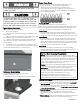
1 Left Frame □ Install (4)M4 × 10 Screws as shown to the leg marked “5A”. Do not fully tighten the screws at this time. Leave 1/8-inch gap below screw head for rail attachment. (A) □ Attach one end of a Side Upper Rail “6A” to the leg, tighten the screws and install and tighten another (1)M4 × 10 Screw.(C) □ Attach one end of a Side Lower Rail “6B” to the leg and tighten the screws. (C) □ Install (4)M4 × 10 Screws as shown to the leg marked “5B”. Do not fully tighten the screws at this time.
2 Right Frame □ Install (4)M4 × 10 Screws as shown to the leg marked “5C”. Do not fully tighten the screws at this time. Leave 1/8-inch gap below screw head for rail attachment. (A) □ Attach one end of a Side Upper Rail “6A” to the leg, tighten the screws and install and tighten another (1)M4 × 10 Screw.(C) □ Attach one end of a Side Lower Rail “6B” to the leg and tighten the screws. (C) □ Install (4)M4 × 10 Screws as shown to the leg marked “5D”. Do not fully tighten the screws at this time.
3 Bottom Shelf □ Install (4)M4 × 10 Screws as shown to Right Frame. Do not fully tighten the screws at this time. Leave 1/8-inch gap below screw head for panel attachment. (A) □ Install (4) M4X10 screws as shown to Left Frame. Do not fully tighten screws at this time. Leave 1/8-inch gap below screw head for panel attachment. (B) □ Attach Bottom Shelf to Right Frame with (3) M4X10 screws. Do not yet fully tighten these screws. (A) □ Attach Bottom Shelf to Left Frame with (3) M4X10 screws.
4 Front Panel □ Attach the two front panel sections together into a single front panel with (1) M4X10 screw as shown. □ Attach the front panel to the cart by slipping the four panel holes on each side over and down onto the four protruding screw heads on the left and right frames. Leave the top screw loose on each side, and fully tighten the other three screws on each side. □ Slide one end of the Right Drip Tray Support Bar “7A” under the front Right Frame top screw. Fully tighten the screw.
5 Wheels to Cart □ Turn cart upside down and attach Legs to Bottom Shelf with (4) M6X13 screws as shown. (A) □ Tap both Leg Extenders onto Left Legs. (B) □ Remove hitch pin, nut and washer from axle rod. Insert axle rod through Wheels and Right Leg Frame. Reattach washer, nut and hitch pin. (C) Note: The convex side of the wheel must face to the cart, and the concave side must face outward. □Stand cart right side up and fully tighten the (6) M4X10 bottom shelf screws.
6 Grill Head to Cart □ This step requires two people to lift and position grill head onto cart. □ Remove the tie wraps and packaging material from regulator hose, side burner valve and igniter wire. Pull hose and igniter wire out to side of grill head. □ Carefully lower the grill head onto the cart. Make sure the regulator hose and igniter wire are hanging outside the cart. □ Line up control panel so that it is flush with front panels. Attach head to cart with (4) M6X13 screws.
7 Left Side Shelf □ Attach fascia to left side shelf with (2) M5x10 screws and M5 flat washers. (A) □ Attach Side Shelf Support Angle Bar with (4) M4x10 screws.(B) □ Hang shelf onto brackets on left side of firebox. □ Attach shelf to firebox as follows: - From inside to outside of firebox with (2) M6x13 screws and M6 compression washers. (C) - From outside to inside of firebox with (2) M6x13 screws. (D) □ Attach fascia to control panel with (1) M4x10 screw.
8 Right Side Shelf □ Remove side burner grate from side burner before assembling and attaching the right side shelf, □ Attach fascia to right side shelf with (2) M5x10 screws and M5 flat washers.(A) □ Attach Side Shelf Support Angle Bar with (4) M4x10 screws.(B) □ Hang right side shelf onto the brackets on right side of firebox. □ Attach shelf to firebox as follows: - From inside to outside of firebox with (2) M6x13 screws and M6 compression washers.
9 Side burner □ Loosen side burner in side shelf. (B ). To loosen, unscrew and remove two front screws and washers holding sideburner in place. (A). Note: Do not loosen electrode screw. □ Remove the 2 pre-installed screws from the valve stem and set them aside. (C) □ Insert valve stem through hole in fascia. (D). Install previously removed 2 screws .Note: Leave a 1/8-inch gap below the screw heads for bezel attachment. (E). □ Attach bezel to fascia and valve face with the installed screws.
10 Heat Diffusers, Cooking Grates and Warming Rack □ Place Heat Diffusers over burners. Diffusers will fit in firebox in either direction. □ Place Cooking Grates onto grate rests at front and rear of Firebox. □ Insert warming rack into brackets at top of Firebox with Curved edge to front as shown. 146.
11 Drip Tray, Drip Cup and LP Tank □ Attach Back Rail to the Cart and Grill Head with (4)M4 × 10 Screws as shown.(A) □ Remove the cotter key and retention pin from the hose bracket on cart right leg. Insert hose into bracket and replace cotter and pin. □ Hang Drip Cup Clip from bottom of drip tray, and insert Drip Tray into bottom of Firebox from back of cart. Fit Drip Cup into Drip Cup Clip. Insert Match Holder Chain into hole in Front Left Leg.
EMERGENCIES: If a gas leak cannot be stopped, or a fire occurs due to gas leakage, call the fire department. Problem Gas leaking from cracked/cut/burned hose. Gas leaking from LP cylinder. Gas leaking from LP cylinder valve. Possible Cause • Damaged hose. • Mechanical failure due to rusting or mishandling. • Failure of cylinder valve from mishandling or mechanical failure. Gas leaking between LP cylinder and regulator connection. • Improper installation, connection not tight, failure of rubber seal.
Troubleshooting (continued) Problem Burner(s) will not light using igniter. (See Electronic Ignition Troubleshooting also) Burner(s) will not match light. Sudden drop in gas flow or low flame. Possible Cause ELECTRONIC IGNITION: • No spark, no ignition noise. • No spark, some ignition noise. • Sparks, but not at electrode or at full strength. • See “GAS ISSUES:” on previous page. • Match will not reach. • Improper method of match-lighting. • See Section I of Electronic Ignition System.
Troubleshooting - Electronic Ignition Problem (Ignition) Possible Cause SECTION I No sparks appear at any electrodes when control knob turned to HI: no noise can be heard from spark module. Check Item • Battery not installed properly. • Check battery orientation. • Dead battery. • Has battery been used previously? • Button assembly not installed properly.
ÍNDICE DE MATERIAS Por su propia seguridad . ... Centro de servicio para parrillas.. . . Información de inscripción de la garantía . . . . . 32 . . 32 . 32 Símbolos de seguridad . . . . . 32 Medidas de seguridad para la instalación . . . . . 32 Garantía para la parrilla Kenmore . . . . . 34 Uso y mantenimiento . . . Lista de piezas . . . Vista esquemática de las piezas . . . Armado . . .
UOS Y MANTENIMIENTO Tanque de gas propano • El cilindro de gas LP con la parrilla debe cumplir los siguientes requisitos: • NUNCA guarde un cilindro de gas de repuesto debajo o cerca del aparato o en un areacerrada. • Nunca llene un cilindro más allá del 80% completo. • Si la información en los dos puntos anteriores no se siguen exactamente, un incendio causando la muerte o pueden producir lesiones graves.
Cambio del tanque de gas • Muchos comerciantes minoristas que venden parrillas, le ofrecen la opción de cambiar su tanque de gas vacío mediante un servicio de recambio. Emplee únicamente empresas de recambio de buena reputación, que inspeccionen, carguen con precisión, verifiquen y certifiquen sus cilindros. Cambie su tanque sólo por otros tanques equipados con el dispositivo de seguridad volumétrica que se describe en la sección de Tanques de gas de este manual.
Prueba para detectar fugas de las válvulas, las mangueras y el regulador Sostenga la tuerca de unión y el regulador, como se ilustra, para conectarlos bien a la válvula del tanque. 6. Gire la tuerca de unión en el sentido de las agujas del reloj, apretándola hasta que no se mueva más. El regulador formará un sello en el dispositivo de seguridad de la válvula del tanque, lo que creará cierta resistencia.
ADVERTENCIA Para usar su parrilla en forma segura y para evitar lesiones graves: • No deje que los niños usen la parrilla ni que jueguen cerca de la misma. • Mantenga el área de la parrilla limpia y sin materiales combustibles. • No obstruya los agujeros laterales ni los de la parte posterior de la parrilla. • Revise periódicamente las llamas del quemador. • Use la parrilla sólo en lugares bien ventilados.
ADVERTENCIA Gire los controles y la fuente de gas o el tanque a la posición OFF cuando no esté en uso. Comprobación de llama del quemador • Retire las parrillas de cocción y los difusores de calor. Quemadores de luz, gire perillas de HI a LO. Debería ver una llama más pequeña en la posición LO que se ve en HI. Realice la verificación de la llama del quemador en el quemador lateral, también. Siempre revise la llama antes para cada uso.
• Piezas plásticas: Lávelas con agua jabonosa tibia y séquelascon un paño • Superficies de porcelana: Debido a su composición vítrea, la mayoría de los residuos se puede eliminar con un paño empapado en una solución de bicarbonato de soda y agua, o con un limpiador especialmente formulado. Use un polvo limpiador no abrasivo para las manchas difíciles de eliminar. • Superficies pintadas: Lávelas con un detergente suave o un limpiador no abrasivo y agua tibia jabonosa. Séquelas con un paño suave, no abrasivo.
B A Cocina indirecta Las aves de corral y los grandes cortes de carne se cocinan lentamente a la perfección en la parrilla por calor indirecto. Coloque los alimentos sobre los quemadores sin encender; el calor de los quemadores iluminados circula suavemente por toda la parrilla, cocinando carne o aves sin tocar una llama directa. Este método reduce en gran medida los brotes cuando se cocinan cortes grasos extra porque no hay llama directa para encender las grasas y los jugos que gotean durante la cocción.
LISTA DE PARTES Clave Descripción Qty Numero de parte Clave Descripción Qty Numero de parte 1 Tapa del quemador lateral 1 40800065 31 Estantería del fondo 1 52200073 2 Rejilla del quemador lateral Rote la vara, la tapa del quemador lateral Lado de la base del quemador 1 40800119 32 Panel frontal 2 40600028Z 2 40800118 33 Lado inferior del carril 2 52200064 1 52200052 34 El lado superior del carril 2 52200061 Quemador lateral Encendedor de alambre, quemador latera Encended
DIAGRAMA DE PIEZAS 54 53 52 55 51 50 49 48 47 46 56 57 58 59 60 61 1 2 3 4 5 6 7 8 9 45 44 43 42 41 40 39 38 37 36 35 34 33 32 31 30 10 11 12 13 14 15 16 17 18 19 20 21 22 23 24 25 29 28 27 26 146.
ANTES DE MONTAJE AVISO: Una vez que usted haya desempaquetado la parrilla según las instrucciones de la HOJA de la PARADA, compruebe todas las piezas de la parrilla contra los cuadros en esto y las dos páginas siguientes. Si usted parte es que falta o dañado, la llamada 1-888-287-0735. 44 • 146.
ANTES DE MONTAJE 146.
ANTES DE MONTAJE 46 • 146.
ASAMBLEA LEA Y REALICE CUIDADOSAMENTE TODAS LAS INSTRUCCIONES DE ASAMBLEA EN LAS PÁGINAS SIGUIENTES. Las herramientas requirieron: El destornillador de la llave ajustable no proporcionada no proporcionado 7/16” la llave combinada (no proporcionada) el hardware siguiente se proporciona en el paquete de ampolla para el uso conveniente.
Marco izquierdo 1 2 □ Instale (4) M4 × 10 Tornillos como se muestra en la pata marcada "5A". No apriete completamente los tornillos en este momento. Deje un hueco de 1/8 de pulgada debajo de la cabeza del tornillo para fijar el riel. (A) □ Conecte un extremo de un riel superior lateral "6A" a la pata, apriete los tornillos e instale y apriete otro (1) tornillo M4 × 10.(C) □ Conecte un extremo de un riel inferior lateral "6B" a la pata y apriete los tornillos.
Marco derecho □ Instale (4) M4 × 10 Tornillos como se muestra en la pata marcada "5C". No apriete completamente los tornillos en este momento. Deje un hueco de 1/8 de pulgada debajo de la cabeza del tornillo para fijar el riel. (A) □Conecte un extremo de un riel superior lateral "6A" a la pata, apriete los tornillos e instale y apriete otro (1) tornillo M4 × 10.(C) □Conecte un extremo de un riel inferior lateral "6B" a la pata y apriete los tornillos.
Estantería Del fondo □ Instalar (4) Tornillos M4 × 10, como se muestra a la derecha del marco. No apriete los tornillos en este momento. Deja brecha 1/8-pulgada por debajo de la cabeza del tornillo para la fijación del panel. (A) Instalar (4) tornillos de M4x10 como se muestra a cuadro izquierdo. No apriete los tornillos en este momento. Deja brecha 1/8-pulgada por debajo de la cabeza del tornillo para la fijación del panel. (B) □ Adjuntar estante inferior al cuadro derecho con (3) tornillos de M4x10.
Panel Frontal □ Una las dos secciones del panel frontal en un único panel frontal con (1) tornillo M4X10 como se muestra. □ Coloque el panel frontal a la compra por el deslizamiento de los cuatro orificios del panel en cada lado una y hacia abajo sobre las cabezas de los tornillos que sobresalen cuatro en los bastidores izquierdo y derecho. Deja el tornillo flojo superior de cada lado, y apriete completamente las otras tres tornillos en cada lado.
Wheels to Cart 9 □Girar la cesta al revés y colocar las piernas al estante inferior con (4) M6x13 tornillos como se muestra. (A) □ Toque tanto la pierna extensores en la pierna izquierda. (B) □ Retire el pasador del enganche, la tuerca y la arandela de la varilla del eje. Inserte la varilla del eje del marco ruedas y la pata derecha. Vuelva a colocar la arandela, tuerca y pasador de acoplamiento.
6 Grill cabeza a la Cesta □ Este paso requiere de dos personas para levantar y parrilla posición de la cabeza sobre el carrito. □ Retire las bandas de sujeción y material de embalaje de la manguera del regulador, válvula de quemador lateral y el cable del encendedor. Tire de la manguera y el cable del encendedor hacia el lado de la cabeza de la parrilla. □ Baje con cuidado la cabeza de la parrilla sobre el carrito.
7 Estante lateral izquierdo □ Adjuntar la fascia de la repisa del lado izquierdo con (2) tornillos de M5x10 y arandelas planas M5. (A) □ Una el soporte del estante Angulo de barra con (4) tornillos de M4x10. (B) □ Alinear la fascia lateral y el panel de control. □ Fije la repisa de Firefox de la siguiente manera: - Desde el interior al exterior de Firefox con (2) tornillos de M6x13 y arandelas de compression M6.
8 Estante lateral derecho □ Retire la rejilla del quemador lateral del quemador lateral antes de montar y fijar la repisa del lado derecho, □ Adjuntar la fascia de la repisa del lado derecho con (2) tornillos de M5x10 y arandelas planas M5.(A) □ Una el soporte del estante Angulo de barra con ( ( 4) tornillos de M4x10..(B) □ Repisa del lado derecho se bloquea en los soportes en el lado derecho de la caja de fuego.
Quemador lateral □ Afloje el quemador lateral en el estante lateral. (B). Para aflojar, desatornille y quite los dos tornillos y arandelas frontales sosteniendo el patilla en su lugar. (A). Nota: No afloje el tornillo del electrodo. □ Retire los 2 tornillos preinstalados del vástago de la válvula y déjelos a un lado. (C) □ Inserte el vástago de la válvula a través del orificio en la fascia. (D). Instale los 2 tornillos quitados previamente.
Los difusores de calor, parrillas de cocción y rejilla de calentamiento □ Coloca difusores de calor sobre los quemadores. Los difusores se ajuste en la cámara de combustión en cualquier dirección. □ Coloque las rejillas para cocinar sobre la rejilla descansa en la parte delantera y trasera de la cámara de combustión. □ Inserte la rejilla para calentar en los soportes en la parte superior de la cámara de combustión con el borde curvado hacia delante como se muestra. 146.
Bandeja De Goteo, Goteo De La Taza y Tanque De Gas Propano □ Una el riel al carrito and Grill Cabeza con (4) tornillos M4 × 10 como se muestra.(A) □ Retire la chaveta y el pasador de retención del soporte de la manguera en el carro de la pierna derecha. Introduzca la manguera en el soporte y vuelva a colocar la chaveta y el pin.
EMERGENCIAS: Si no se puede detener una fuga de gas, o si ocurre un incendio debido a una fuga de gas, llame a los bomberos. Emergencias Fuga de gas de mangueras quebradas, cortadas o quemadas. Causas probables • Manguera dañada. Medidas de prevención / solución • Cierre el gas en el cilindro o en la fuente de los sistemas de gas natural. Si tiene todo tipo de desperfectos, pero no está quemada, cambie la válvula/la manguera/ el regulador.
Resolucion de problemas (continuacion) Problema El quemador o los quemadores no se enciende(n) al usar el encendedor. Pro Causas probables • El cable o el electrodo está cubierto con restos de comida. • Los cables están flojos o desconectados. • Los cables producen cortocircuitos (chispas) entre el encendedor y el electrodo. BOTÓ N PULSADOR PIEZOELÉCTRICO Y GIRATORIO: • El botón pulsador se pega en el fondo. • La perilla giratoria gira sin hacer clic. • Hay chispas entre el encendedor y el electrodo.
Resolución de problemas – Encendido electrónico Problema (encendido) Causas probables SECCIÓ N I No aparecen chispas en ningún electrodo cuando se pulsa el botón de encendido; no se oye ningún sonido del módulo de chispas. • La pila no está instalada adecuadamente. • Revise la orientación de la pila. • Pila gastada. • ¿Es una pila usada? Causas probables Procedimiento de revisión • La unidad del botón no • Revise que las piezas estén debidamente enroscadas.
Kenmore ® Customer Care Hotline To schedule in-home repair service or order replacement parts Para pedir servicio de reparación a domicilio, y ordenar piezas 1-844-553-6667 www.kenmore.