AV CONTROL CENTER C-V751 INSTRUCTION MANUAL KENWOOD CORPORATION B60-4341-10 01 CH (T, X) AP 9904
Before applying power power Caution : Read this page carefully toBefore ensureapplying safe operation. Units are designed for operation as follows. Europe and U.K. ........................................................................ AC 230 V only Australia .................................................................................... AC 240 V only For the United Kingdom Factory fitted moulded mains plug 1. The mains plug contains a fuse.
Before applying power Contents Caution : Read the pages marked carefully to ensure safe operation. Before applying power .........................................................................................................................................................................2 Safety precautions.......................................................................................................................................... 2 Unpacking ..............................................
Before applying power System connection 4 Special features True home theater sound DTS DTS (Digital Theater Systems) is a 5.1 channel digital audio format that provides five full-spectrum channels and one low-frequency (subwoofer) channel for unprecedented clarity, optimum channel separation and a (wide) dynamic range. In the DTS mode, the 5.1 channel digital input from a DTS CD, LD or DVD disc (carrying the DTS marking) can be played in Digital Surround.
System connection System connection Connection of audio components (CD player, MD recorder, cassette deck, power amplifier) Make connection as shown below. When connecting the related system components, refer also to the instruction manuals of the related components. Do not plug in the power lead until all connections are completed.
System connection 6 Connection of video components (LD player, VCR, DVD) LD player *1 *1 When using an LD player of Series 21, connect it to the DVD/6CH INPUT. Video OUT Audio OUT When using a cable or satellite tuner, connect it to the VIDEO 2 input. Monitor TV *2 When using DVD 6ch INPUT. 0 Video IN AM ANTENNA VIDEO CD (OPTICAL 1) DVD (COAXAL) UNSWITCHED SYSTEM CONTROL FM 75Ω REC GND PRE OUT PLAY VIDEO 1 PLAY VIDEO 2 FRONT SURROUND CENTER MONITOR DVD/ OUT 6CH.
System connection Digital connections 7 Make connections as shown below. The digital in jacks can accept DTS, Dolby Digital (AC-3) or PCM signals. Connect components capable of outputting DTS, Dolby Digital (AC-3) or standard PCM (CD) format digital signals. When connecting the related system components, be sure to also refer to the instruction manuals supplied with the components you are connecting. Do not connect the power cord to a wall outlet until all connections are completed.
System connection 8 About the system control connections When this unit is connected to KENWOOD audio component system “SERIES 21”, also connect them through the system control cords to allow system-control operations between components. Connection example AM ANTENNA UNSWITCHED SYSTEM CONTROL FM 75Ω GND AV CONTROL CENTER The SERIES 21 components which can be system-connected with this unit include the LD player, MD recorder and DVD player.
System connection Connection of antenna 9 Connection method to each antenna terminal 1 Push lever. 2 Insert cord. 3 Return lever. AM ANTENA FM 75Ω GND AM loop antenna connection The supplied antenna is for indoor use. Place it as far as possible from the main system, TV set, speaker cords and power cord, and set it to a direction which provides the best reception.
Using DVD 6ch INPUT System connection 10 Opening/closing the door 1 Press the ON/STANDBY key to ON. ON/STANDBY 2 Opening/closing the door OPEN/CLOSE Note When opening or closing the door, be careful not to catch your finger in the door. Otherwise there is a risk of injury. Changing the input selection display (AUTO key) To make the system control operation, the input selection display should be switched according to the actually connected components.
Controls and indicators System connection 11 DOLBY DIGITAL indicator TUNED indicator AUTO tuning mode STEREO indicator Memory indicator Frequency display, input selector display, preset channel display, surround mode display SOUND indicator DIGITAL indicator REC indicator CS indicator AUTO indicator DTS indicator RDS indicators AUTO STEREO MEMO. TUNED RDS EON TP PTY TA NEWS MUTE CLIP AUTO SOUND DIGITAL REC DTS DOLBY DIGITAL CS PRO LOGIC 3 STEREO DOWN MIX MHz SLEEP KHz TIMER 1 2 TAPE2/MONI.
Setup of the Graphical Remote Control (GRC) Setup of the Graphicalunit Remote Control (GRC) unit Controls and indicators The Graphical Remote Control (GRC) unit provided with the AV CONTROL CENTER can also control KENWOOD cassette decks, CD player, MD recorder and LD player which are connected to it through system control cords. For details of the controllable functions, refer to the instruction manuals of these components.
Setup of the Graphical Remote Control (GRC) unit Operation of Graphcal Remote Control 13 Perform the following procedure after inserting batteries for the first time and every time after changing them. Loading the batteries Loading batteries 1 Remove the cover. Caution in battery replacement 2 Insert batteries. · 3 Close the cover. ª ÷ Insert 6 AA-size batteries as indicated by the polarity marking.
Setup of the Graphical Remote Control (GRC) unit 14 To adjust the contrast 1 Press the CONTRAST button until “Contrast” message appears on the screen. CONTRAST ENTER 2 While this message is displayed, move the joystick up or down to increase or decrease the contrast until you are satisfied. 3 Press the save the contrast setting and return to the control screen. Backlight botton 1 To use GRC in the dark, press BACKLIGHT .
Setup of the Graphical Remote Control (GRC) unit Setting up the GRC according to other components (Set Up) In the initial condition, the setup codes for CD, MD and DVD have already been pre-registered. The GRC can also be used to remote control other components which are not connected through system control cords. In the operations of the GRC (Graphical Remote Control unit), proceed to each step within 10 seconds after the previous step. The display disappears in 10 seconds.
Setup of the Graphical Remote Control (GRC) unit 16 7 Press the “Code” icon. You can now choose from a list of all the codes available for the device. Select the first code on the list. ÷ When a code which is not shown in the setup code chart is entered, the entered code disappears automatically. ÷ Even when the system control code is connected, some models may not automatically display the “System” screen. ÷ With CD-Carrousel, select “Sys-carrousel”.
Setup of the Graphical Remote Control (GRC) unit 17 5 Repeat steps 2 through 4 until you have taught GRC all the commands you want it to know. If you need more lines, touch or to access more lines. Programming an additional function which is not displayed in the screen 1 Repeat steps 1 and 2 in “To program STOP as a new control item”. ^ 2 Press the “Modify” icon. 3 Press the or “Empty 1 to 8”. icon to select one of 4 Assign a name to the function. ÷ The name can be composed using up to 8 characters.
Remote control of components from the GRC Remote control of components from the GRC Controlling the AV Control Center ENTER UP CONFIRM VO LU The operations required to remote control the AV Control Center includes the INPUT SELECTOR selection, display mode selection, stereo selection and so on. The following procedures show how to remote control the basic operations of the GRC.
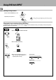
Remote control of components from the GRC Controlling the components connected through system control cords When a CD player, MD recorder, cassette deck and/or DVD player are connected with the AV CONTROL CENTER through system control cords, their system control operations are possible from the GRC. ENTER Preparations ÷ System control connection 8 ÷ Setup of source components% VO LU UP CONFIRM ME DOWN CONTRAST ON/STANDBY BACKLIGHT Select the “music” icon in the Quick access menu.
Remote control of components from the GRC 20 Operating the cassette deck 1 Select the ”music“ icon in the fixed segment screen. (Select the icon) usi ÷ For the operation of the cassette deck, also read the instruction manual of the cassette deck. c m ÷ Any of the cassette deck operation keys can be selected. 2 Select the ”MD/TAPE 1“ icon. Display the cassette deck operation menu. 3 Select the icon to be operated. Select the ”movie“ icon in the Quick access menu.
Remote control of components from the GRC Controlling the other components Operating the Video cassette recorder 1 Select the ”movie“ icon in the fixed segment screen. mo (Select the icon) ÷ Any of the Video operation keys can be selected. ÷ For the operation of the Video cassette recorder, also read the instruction manual of the Video cassette recorder. vie 2 Select the ”VIDEO 1“ icon. Display the Video cassette recorder operation menu. 3 Select the icon to be operatwed.
Convenient functions Remote control of components from the GRC 22 One-touch operation features (Main unit only) (CD player, cassette deck (Single deck only), DVD player) When the system is in standby mode, the operations as described below are possible provided that the associated components are connected through system control cords. Preparations 1 Ensure that system control cords are connected. 2 Load the source component with the software to be played.
Speaker settings Speaker settings Setup for surround play (SET UP) 23 The feeling of presence in the surround effects can be improved by performing the following adjustment procedure according to the speaker system and listening room environment in use. Once they are adjusted, re-adjustment is not necessary even after the surround mode is switched to other modes. When the SERIES 21 speakers are used, the settings in steps 1 and 2 are not necessary.
Speaker settings 24 2 Select a speaker system. GRC GRC 1 Set up the subwoofer. “SW” (Select the icon) Quick setup SW Yes : Subwoofer on SW No : Subwoofer off Custom setup SW On : Subwoofer on SW Off : Subwoofer off 2 Select On or Off. Each press changes the setup. 3 Set up the subwoofer remix. “Remix” (Select the icon) 4 Select On or Off. Each press changes the setup. 5 Set up the front speaker size. “FRNT (L/ R)” (Select the icon) or 6 Select Nml or Lrg. Each press changes the setup.
Speaker settings 25 3 Set the speaker distance. GRC 1 Measure the distance from the listening position to each of the speakers. 2 Select a speaker distance. (Select the icon) Jot down the distance from the listening position to each of the speakers FRONT (L/R) : CENTER (C) : SURROUND (LS/RS) : 3 Set “SP Distance”. (Select the icon) 4 Touch Speaker distance 1 ) F T 3.) M To increase To decrease meter(s) meter(s) meter(s) to select the speaker. 5 Repeat steps 3 and 4 for each speaker.
Speaker settings 26 GRC 3 Adjust the levels of all the speakers than the front speakers (left, right). While test tone is output from a speaker, adjust the volume level of the speaker. (Select the icon) ÷ The test tones is not output from the speaker which has been set to off. "Speaker settings" £ FM AM S MW LW Display when test tone is output from a surround speaker To increase level To decrease level 4 Repeat 3 until all the system's speakers (except the subwoofer) play at the same volume.
Playing music Sound adjustment The following procedure allows to play a MD,CD or cassette tape. 27 Preparations ÷ Connect components as described in “System connection”. 5 ÷ Complete “Setup of the Graphical Remote Control (GRC) unit”. @ 1 Press the ON/STANDBY key to ON. GRC Main unit ON/STANDBY ÷ Load the CD player or cassette deck with the software to be played. \Read the instruction manuals of the associated components. ON/STANDBY 2 Select the input source.
Sound Playing adjustment music To listen through headphones 1 Plug headphones. PHONES 2 Adjust the volume. ÷ The speaker sound is defeated at the moment headphones are inserted into the PHONES jack. ÷ If headphones are plugged in during surround play, its mode is automatically switched to the STEREO mode. If they are plugged in during DVD 6ch INPUT play, only the front L ch and R ch will be played. The previous status resumes at the moment headphones are unplugged.
Sound adjustment Sound adjustment 29 Ajustment for surround play (while listening to music) (SOUND) 1 Adjusting the tone (Stereo status only) GRC 1 Enter the SOUND adjustment mode. so (Select the icon) un d Main unit Each press of the SOUND key switches the indication. 1 2 3 4 5 6 BASS TREBLE C LS/RS SW MIDNIGHT : : : : : Tone, Bass Tone, Treble Center speaker Surround speaker, Left/Right Sub woofer ÷ Adjustments 1 and 2 are not available in other modes than STEREO and “Tone” is set to “On”.
Sound adjustment 30 2 Adjust the center speaker level. “C” Main unit center speaker level (Select the icon) TEREO TUNED F M N TP A M NEWS MW CLIP LW 3 Adjust to the desired level by pressing keys and Cch +2 AUTO SOUND DTS DOLBY PRO LOGIC MHz SLEEP KHz TIMER 1 2 ÷ The level can be adjusted between -10 and +10 in step of 1. 4 Adjust the surround speaker level.
Recording Recording When recording sound with a recorder component of KENWOOD, synchro recording is possible by setting the INPUT SELECTOR to select MD or TAPE 1 according to the connected component. 31 Sound may not be reproduced when the input signal and LISTEN MODE are selected improperly. How to select the digital input, analog input and LISTEN E MODE. Recording an analog input source 1 To record a music source Main unit Main unit GRC e 1 Select the ”edit“ icon in the fixed segment screen.
Recording 32 2 Select the ANALOG input mode. GRC Main unit INPUT MODE 1 Set the input mode to ANALOG. (Select the icon) Main unit Each press switches the indication. 1 DIGITAL AUTO 2 DIGITAL MANUAL 3 ANALOG GRC Select the icon of the source to be played. ÷ The switching is not available when the DVD 6ch INPUT is selected. • ÷ “3 ANALOG” cannot be selected when the input signal is the DTS signal. or switches the display between “Source” ÷ Each press of and “Destination” alternately.
Recording When recording sound with a recorder component of KENWOOD, synchro recording is possible by setting the INPUT SELECTOR to select MD or TAPE 1 according to the connected component. 33 Sound may not be reproduced when the input signal and LISTEN MODE are selected improperly. How to select the digital input, analog input and LISTEN E MODE. Recording a digital input source (CD,DVD) 1 To record a music source Main unit Main unit GRC e 1 Select the ”edit“ icon in the fixed segment screen.
Recording 34 2 Set the input mode to DIGITAL AUTO (MANUAL). GRC Main unit INPUT MODE 1 Set the input mode to “DIGITAL AUTO (MANUAL)”. (Select the icon) Main unit Each press switches the indication. 1 DIGITAL AUTO Input signal is detected automatically. 2 DIGITAL MANUAL Selected input signal is held. 3 ANALOG GRC 1 DIGITAL AUTO 2 DIGITAL MANUAL Input signal is detected automatically. Selected input signal is held. ÷ The switching is not available when the DVD 6ch INPUT is selected.
Recording 35 GRC e 1 Select the ”edit“ icon in the fixed segment screen. t (Select the icon) di GRC Select the icon of the source to be played. 2 Select the source to be recorded. Select an input source other than MD/TAPE 1. ÷ For the recording using a cassette deck or MD recorder, read the instruction manual of the MD recorder or cassette deck. ÷ The input is automatically down-mixed to 2 channels. ÷ Recording is not available when the DVD 6ch INPUT is selected.• 3 Select the “Distination”.
Recording 36 4 Start recording. Main unit GRC 1 Press the “Src.” icon. 2 Pause the playing the source from beginning of the track being recorded. 3 Play the source and start recording.
Recording 37
Listening to radio broadcasts 38 Listening to radio broadcasts Radio stations can be classified into RDS (Radio Data System) stations and other stations. For listening to RDS stations or storing RDS stations in preset memory, see section entitled “Functions of RDS”. · Tuning radio stations 1 Select the TUNER input. Main unit GRC Main unit (Select the icon) INPUT usi c m Each press switches the indication.
Listening to radio broadcasts Functions of RDS (Radio Data System) 39 RDS is a system which transmits useful information (digital data) for FM broadcasts together with the broadcast signal. Tuners and receivers designed for RDS reception can extract the information from the broadcast signal for use with various functions such as automatic display of the station name. Functions made possible with RDS The RDS indicator lights up when an RDS broadcast (signal) is received.
Listening to radio broadcasts 40 Use the operating procedure on this page to store RDS stations automatically in preset memory. Up to 40 RDS stations can be preset and received with a simple key operation. This unit is compatible with the RDS so it can use convenient RDS functions including automatic tuning and EON reservation. RDS stations should be stored in the preset memory following the procedure in “Presetting RDS stations” before listening to RDS stations.
Listening to radio broadcasts The AUTO MEMORY function gives precedence to RDS stations and assigns them from preset number 1. Therefore, when it is required to preset RDS stations as well as non-RDS stations, execute the AUTO MEMORY operation first then proceed to the manual memory operation of non-RDS stations.
Listening to radio broadcasts 42 GRC 9 Press the “Enter” icon to enter in memory. (Select the icon) ÷ To preset other stations, repeat 6 to 9 for each of them. 0 Press the “Enter” icon. Receiving all preset stations in order (P. CALL) GRC 1 Select the preset number of the desired or . station by pressing (Select the icon) ÷ Every time the key is pressed, the next station in the order of the preset number is received. When you press key, ...................................
Listening to radio broadcasts By specifying the type of program (genre) you want to listen to, the tuner automatically searches for a station which is currently broadcasting a program of the specified type. 43 With certain receiving conditions, it may take more than 1 minute until the search completes. Preparation ÷ Preset RDS stations with the AUTO ‚ MEMORY function. ÷ Select the TUNER input. ‚ ÷ Set the receiving band to FM.
Listening to radio broadcasts 44 3 Start the search. Main unit GRC (Select the icon) When searching for a Rock Music broadcast. Display while the tuner is searching. AUTO STEREO MEMO. TUNED F M RDS EON TP A M PTY TA NEWS MW MUTE CLIP LW RDS PTY Blinks ROCK M AUTO DTS PRO L MHz KHz T Program type name display. When a station is received. AUTO STEREO MEMO. TUNED F M RDS EON TP A M PTY TA NEWS MW MUTE CLIP LW Goes off To change to a different program type: Repeat steps 1, 2, 3.
Listening to radio broadcasts When the receiver is tuned to a RDS EON station (a station at which the EON indicator lights up), this function lets you set the receiver to automatically switch stations to receive news or traffic programs as they are broadcast. When the broadcast is over, the receiver returns to the original station automatically. Preparation Perform steps 1 to 3 of “Presetting RDS stations (AUTO MEMORY)”.
Listening to radio broadcasts 46 3 Select the desired kind of program. Display when “TA” is selected GRC Main unit AUTO STEREO MEMO. TUNED F M RDS EON TP A M PTY TA NEWS MW MUTE CLIP LW (Select the icon) BBC 2 FM AUTO DTS PRO MHz KHz “TP” lights for stations where TP (Traffic Program) can be received. RDS TA/NEWS Each press switches the indication.
Listening to radio broadcasts 47
Ambience effects 48 Listening to radio broadcasts This AV CONTROL CENTER incorporates 7 different sound modes to let you enjoy surround sound with a wide variety of program sources. The Dolby Digital (AC-3) and Dolby Pro Logic surround sound let you enjoy theater-like surround effects when you play Dolby Digital (AC-3) and Dolby Surround program sources (like Laserdiscs and DVDs). Dolby 3 Stereo creates a panoramic frontal sound field.
Listening toAmbience radio broadcasts effects 49 Dolby Pro Logic Dolby Pro Logic is a specially encoded 2 channel surround format designed to provide theaterlike surround sound from Dolby Surround encoded sources (such as video and Laserdisc ). This AV CONTROL CENTER is equipped with a Dolby software marked Pro Logic surround decoder to let you enjoy the wide variety of currently available Dolby Surround home video software.
Ambience effects D I G I T A L Preparations ÷ Turn ON related components. ÷ Complete "Setup for surround play". £ ÷ Set the INPUT SELECTOR to the component you wish to play back with surround sound. ÷ Use the INPUT MODE key to select the input mode (analog or digital) for the source you wish to play back. * Sound may not be reproduced when the input signal and Listen mode are selected improperly. How to select the digital input, analog input and LISTEN MODE.
Ambience effects 51 GRC c To select the Circle surround mode: (Select the icon) 1 Select the Circle surround type. (Select the icon) or To end surround play Main unit GRC 1 Select the “Stereo” icon.
Ambience effects 52 To select the DSP mode (DSP) 1 Select the DSP surround mode. GRC ÷ This can be selected when the input signal is other than DTS, Dolby Digital (AC-3). l isten 1 Select DSP. (Select the icon) mode Main unit Each press LISTEN MODE key switches the indication. 1 2 3 4 5 6 7 8 2 Select the “Arena” “Theater” “Jazz Club”. (Select the icon) PRO LOGIC 3 STEREO CS CINEMA CS MUSIC ARENA THEATER JAZZ CLUB STEREO ÷ 2 cannot be selected when “C” has been set to Off in the Setup operation.
Ambience effects Listen mode selection 53 Surround play of digital input INPUT selector DVD (COAXIAL), CD (OPTICAL) Input signal DTS Dolby digital *1 1 DTS 2 STEREO 1 2 3 4 Listen mode PCM *1 1 2 3 4 5 6 7 8 DOLBY DIGITAL PRO LOGIC 3 STEREO STEREO PRO LOGIC 3 STEREO CS CINEMA CS MUSIC ARENA (DSP) THEATER (DSP) JAZZ CLUB (DSP) STEREO Surround play of analog input INPUT selector DVD 6ch INPUT Input signal MD/TAPE1, VIDEO1, 2, CD, TUNER Analog Analog *1 The switching is not available when t
Clock adjustment 54 Timer operation This unit incorporates a clock function. Be sure to adjust the correct time before using the timer function. The time display blinks after a power failure or when the power cord has been unplugged from the AC outlet and plugged in again. In such a case, adjust the clock again. Clock adjustment (Main unit only) 1 Activate the clock adjustment mode. Main unit 1 Press the CLOCK key. CLOCK 2 Enter the hour. Main unit MULTI.
Timer operation Timer operation Two 24-hour timer systems (TIMER 1, TIMER 2) (which can be used every day) and a sleep timer system (which works only once) are available. In each of TIMER 1 and TIMER 2, the timer data including the operating period and played contents can be set and selected to be activated or not as required. Timer reservation is possible for the two types TIMER 1 and TIMER 2 at the same time.
Timer operation 56 5 Enter the On time (Minute). Main unit MULTI.CONTROL LEVEL To decrease the figure 1 Set the figure of minute. ÷ After entering the figure of “hour” with the procedure in step 5, enter the figure of “minute” using the same procedure. To increase the figure TIMER SET A M 1 ): 1 ) AUTO SOUND DIGITAL R DTS DOLBY DIGITAL PRO LOGIC 3 STER DOWN M MHz SLEEP KHz TIMER 1 2 TAPE2/MO 2 Enter the figure in memory. ÷ If you make a mistake, restart from step 3. 6 Enter the OFF time (Hour).
Timer operation 57 8 Make the desired reservation. For timer playback Timer recording of broadcasts Main unit Main unit 1 Select the mode. MULTI.CONTROL LEVEL Up Down 1 Select the mode. 1 Select “PLAY” (Each press alternates them.) PLAY : At the ON time, playback starts. REC O D FM TIMER SET AM S MW LW 2 Enter it. MULTI.CONTROL PLAY AUTO SOUND DIGIT DTS DOLBY DIGIT PRO LOGIC 3 DOW MHz SLEEP KHz TIMER 1 2 TAPE LEVEL Down Up 1 Select “REC”. (Each press alternates them.
Timer operation 58 Check the reservation content. Each press of the key switches the TIMER numbers as follows. Main unit TIMER MODE Select the TIMER number to be checked. 1 TIMER 1 ...... (Contents of the timer 1 are displayed.) 2 TIMER 2 ...... (Contents of the timer 2 are displayed.) 3 TIMER 1, 2 .. (Contents of the timer 1 and timer 2 are displayed.) 4 Off ÷ The reserved contents will be displayed for 2 seconds per item. After this, the previous display content appears again.
Timer operation 59
Important items 60 Maintenance Maintenance of the unit When the front panel or case becomes dirty, wipe with a soft, dry cloth. Do not use thinner, benzine, alcohol, etc. for these agents may cause discoloration. In regard to contact cleaner Do not use contact cleaners because it could cause a malfunction. Be specially careful not to use contact cleaners containing oil, for they may deform the plastic component. Reference Manufactured under license from Dolby Laboratories.
In case of difficulty What appears to be a mulfunction may not always be serious. If your unit should not perform as expected, consult the table below to see if the problem can corrected before seeking help from your dealer or service representative. How to reset the microcomputer 1 Unplug the power cord from the wall outlet. (ON/STANDBY) key depressed, 2 While holding the plug the power cord into the wall outlet again.
In case of difficulty 62 Remote control unit Symptom Cause Remedy ÷ Batteries are exhausted. ÷ The remote control unit is too far away from the main system, controlling angle is too large, or there is an obstacle in between. ÷ The audio cords and system control cords are not connected properly. ÷ The source component to be operated does not contain the tape(s) or disc. ÷ Replace with new batteries. # ÷ Operate the remote control unit within the controllable range. @ The GRC screen is not displayed.
Specifications Caution : Read this page carefully to ensure safe operation. 63 For C-V751 Audio section AM Tuner section (for Australia) Total harmonic distortion (1 kHz, 1V) ...................................................................................... 0.01 % Signal to noise ratio (IHF’66) CD .................................................................................. 93 dB Input sensitivity / impedance CD ..................................................................
For your records Record the serial number, found on the back of the unit, in the spaces designated on the warranty card, and in the space provided below. Refer to the model and serial numbers whenever you call upon your dealer for information or service on this product.