DUAL FUEL DOUBLE OVEN COOKER CK 740 Instructions for use - Installation advice
CONTENTS Introduction . . . . . . . . . . . . . . . . . . . . . . . . Important Safeguards & Recommendations . . . Cooking Hob Key . . . . . . . . . . . . . . . . . . . . Control Panel . . . . . . . . . . . . . . . . . . . . . . . How to use the cooking hob . . . . . . . . . . . . . How to use the multi-function oven. . . . . . . . . How to use the conventional oven . . . . . . . . . How to use and set the electronic programmer . Cleaning & maintenance. . . . . . . . . . . . . . . . . . . . . . . . . . .
Dear Customer, Thank you for purchasing a Kenwood Dual Fuel Double Oven Cooker The safety precautions and recommendations in these instructions are for your own safety and that of others. They will also provide a means by which to make full use of the features offered by your appliance. Please keep this booklet in a safe place. It may be useful in the future, either to yourself or to others in the event that doubts should arise relating to its operation.
IMPORTANT SAFEGUARDS AND RECOMMENDATIONS ● Fire risk! Do not store flammable After unpacking the appliance, check to ensure that it is not damaged and that the oven door closes correctly. If in doubt, do not use and consult your supplier or a professionally qualified technician. Packing materials (i.e. plastic bags, polystyrene foam, nails, packing straps, etc.) should not be left around within easy reach of children, as these may cause serious injuries.
1 - COOKING HOB 2 1 3 4 5 6 Fig. 1.1 COOKING HOB 1. 2. 3. 4. 5. 6.
2 - CONTROL PANEL Fig. 2.1 A U T O 9 8 12 7 6 5 4 3 2 1 11 13 10 CONTROL PANEL - Controls description 1. 2. 3. 4. 5. 6. 7. 8. 9. 10. 11.
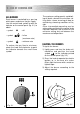
3 - USE OF COOKING HOB GAS BURNERS Each burner is controlled by a gas tap which opens and closes the gas supply. Line the control knob symbol up with the indicator on the control panel (fig. 3.1) to obtain: – symbol ● : off – symbol : full on (maximum rate) – symbol : minimum rate To reduce the gas flow to minimum, rotate the knob anti-clockwise to point the indicator towards the small flame symbol.
DEEP FAT FRYING For safety purposes when deep fat frying, do not fill the pan more than one third full of oil. DO NOT cover the pan with a lid and DO NOT leave the pan unattended. In the unfortunate event of a fire, leave the pan where it is and turn off the control knobs. Place a damp cloth or lid over the pan to smother the flames. Leave the pan to cool for at least 30minutes before moving the pan. DO NOT USE WATER ON THE FIRE.
CORRECT USE OF TRIPLE-RING BURNER (Fig. 3.5a - 3.5b) Flat-bottomed pans should be placed directly onto the pan-support. When using a WOK always place the supplied stand in position over the burner to maintain the correct operation of the triple-ring burner (Fig. 3.5a - 3.5b). WRONG Fig. 3.5a 10 CORRECT Fig. 3.
4 - MULTI-FUNCTION MAIN OVEN Attention: the oven door becomes very hot during operation. Keep children away. Heating and cooking in the MULTIFUNCTION oven are obtained in the following ways: a. by normal convection The heat is produced by the upper and lower heating elements. GENERAL FEATURES The multi- function oven can be programed for 7 different functions to satisfy every cooking need.
50 75 100 250 200 1 25 225 175 150 Fig. 4.1 TEMPERATURE KNOB (fig. 4.2) To turn on the heating elements of the oven, set the switch knob on the desired program and select the required temperature. To set the temperature, line up the temperature knob indicator with the required temperature. The elements will turn ON or OFF automatically according to the energy need which is determined by the thermostat. Fig. 4.2 FUNCTION SELECTOR KNOB (fig. 4.
GRILLING The infra-red heating element is switched on. The heat is diffused by radiation. Use with the oven door closed and the temperature knob between 50° and 225°C for a maximum of 15 minutes. Note: It is recommended that you do not grill for longer than 30 minutes at any one time. Attention: the oven door becomes very hot during operation. Keep children away.
VENTILATED GRILL COOKING The infra-red ray grill and the fan are on. The heat is mainly diffused by radiation and the fan then distributes it throughout the oven. The temperature must be set between 50° and 175 °C for max 30 minutes. It is necessary to preheat the oven for about 5 minutes. Use with the oven door closed. Attention: the oven door becomes very hot during operation. Keep children away. For correct use see “GRILLING AND “AU GRATIN”.
COOKING ADVICE GRILLING AND “AU GRATIN” OVEN COOKING Before introducing the food, preheat the oven to the desired temperature. For a correct preheating operation, it is advisable to remove the tray from the oven and introduce it together with the food, when the oven has reached the desired temperature. ROASTING To obtain classical roasting, it is necessary to remember: – that it is advisable to maintain a temperature between 180 and 200 °C.
COOKING GUIDE Temperature and times given are approximate, as they will vary depending on the quality and amount of food being cooked. Remember to use ovenproof dishes and to adjust the oven temperature during cooking if necessary.
5 - CONVENTIONAL OVEN Attention: the oven door becomes very hot during operation. Keep children away. GENERAL FEATURES The conventional oven has 3 heating elements which are: – Top element 700 W – Bottom element 800 W – Grill element 1600 W NOTE: Upon first use, it is advisable to operate the oven for 30 minutes in the position and for another 30 minutes at the maximum (temperature knob on position 250) in the position , to eliminate possible traces of grease on the heating elements.
50 200 5 12 225 100 250 175 150 Fig. 5.1 Fig. 5.2 FUNCTION SELECTOR KNOB (fig. 5.1) TEMPERATURE KNOB (Fig. 5.2) Rotate the knob clockwise to set the oven for one of the following functions. This only sets the cooking temperature and does not switch the oven on. Rotate clockwise until the required temperature is reached (from 50 to 250°C). The light above the function selector will illuminate when the oven is switched on and turns off when the oven reaches the correct temperature.
PLATE WARMING The upper and lower heating elements are switched on; the heat is diffused by natural convection. The temperature knob must be set to position to heat the plates at about 60°C. This function can also be used for traditional convection cooking: the temperature knob must be set between 50 and 250°C. Recommended for: Dish warming using the special rack. For correct use see “USE OF SPECIAL DISH RACK”. KEEP ATTENTION: Plates are hot after warming.
COOKING GUIDE Temperature and times given are approximate, as they will vary depending on the quality and amount of food being cooked. Remember to use ovenproof dishes and to adjust the oven temperature during cooking if necessary.
USE OF THE GRILL ROTISSERIE (Fig. 5.3) The oven is equipped with a rotisserie for spit roast cooking using the grill. The rotisserie consists of: – an electrical motor mounted on the rear part of the oven – stainless steel spit with a removable stay-cool handle and two adjustable sets of prongs – spit support to be inserted in the central guide of the oven. The rotisserie motor is operated by the switch knob on grill position . Preheat the oven for about 5 minutes.
USE OF SPECIAL DISH RACK This special shelf can be used as a dish rack or when turned over, as a normal shelf for oven cooking. It must be inserted between the guides of the lateral racks. USING THE SPECIAL RACK FOR NORMAL COOKING Slide in the shelf on the guides: the safety catch must be turned toward the oven base (see detail of figure 5.5).
6 - ELECTRONIC PROGRAMMER The electronic programmer performs the following functions: – 24 hours clock with illuminated display – Timer (up to 23 hours and 59 minutes) – Program for automatic oven cooking – Program for semi-automatic oven cooking. Description of the illuminated symbols: AUTO - flashing - Programmer in automatic position but not programmed AUTO - always lit - Programmer in automatic position with program set.
ELECTRONIC CLOCK (fig. 6.2) The programmer is equipped with an electronic clock with an illuminated display which indicates hours and minutes. Upon immediate connection of the oven or after a powercut, three zeros will flash on the display panel. To set the hour it is necessary to push the button and then the or button until you have set the exact hour (fig. 6.2). Another way is to simultaneously push the two buttons and at the same time push the or button. Note: The hour setting deletes any program.
AUTOMATIC OVEN COOKING To cook food automatically in the oven, it is necessary to: 1. Set the length of the cooking time 2. Set the end of the cooking time 3. Set the temperature and the oven cooking program. These operations are done in the following way: 1. Set the length of the cooking time by pushing the button and the button to advance, or to go back if you have passed the desired time (fig. 6.5). The AUTO and the symbol will be on. 2.
SEMI - AUTOMATIC COOKING This is used to switch the oven off automatically after the desired cooking time has elapsed. There are two ways to set the semiautomatic cooking function: 1. Set the length of the cooking time by pushing the button and the button to advance, or to go backwards (Fig. 6.7). This sets the desired “stop” time. At the end of the cooking, the oven and the symbol will turn off, the AUTO will flash and a buzzer will go off which can be stopped by pushing any of the buttons.
7 - CLEANING AND MAINTENANCE Important: Before cleaning or carrying out any maintenance disconnect the appliance from the electrical supply and wait for it to cool down. Attention The appliance gets very hot, mainly around the cooking areas. It is very important that children are not left alone in the kitchen when you are cooking. Do not use a steam cleaner because the moisture can get into the appliance thus make it unsafe.
BURNERS The burners can be removed and washed with soapy water only. They will remain perfect if always cleaned with products used for silverware. After cleaning, check that the burnercaps and burner-heads are dry before placing them in the respective housings. Note: To avoid damage to the electric ignition do not use it when the burners are not in place.
TRIPLE RING BURNER The triple ring burner must be correctly positioned (see fig. 7.2 - 7.3); the burner rib must be enter in their logement as shown by the arrow. Then position the cap A and the ring B (fig. 7.3). The burners must be correctly positioned so that they cannot rotate (fig. 7.3). Fig. 7.4 Fig. 7.
Fig. 7.6 OVEN DOOR STORAGE COMPARTMENT The internal glass panel can be easily removed for cleaning by unscrewing the 2 retaining screws (Fig. 7.6) The storage compartment is accessible through the pivoting panel (fig. 7.7). Do not store flammable material in the oven or in the storage compartment. 30 Fig. 7.
INSIDE OF OVEN This must be cleaned every time it is used. Remove and refit the side runner frames as described in the next section. With the oven warm, wipe the inside walls with a cloth soaked in very hot soapy water or another suitable product. The bottom of the oven, side runner frames, tray and rack can be removed and washed in the sink. FITTING THE OVEN OUT – Hang up the wire racks “G” on the oven walls interposing the self cleaning panels “A” (fig. 7.8) – Slide the required shelf and tray etc.
REMOVING THE OVEN DOOR Fig. 7.10A The oven door can easily be removed as follows: – Open the door to the full extent (fig. 7.10A). – Attach the retaining rings to the hooks on the left and right hinges (fig. 7.10B). – Hold the door as shown in fig. 7.10. – Gently close the door and withdraw the lower hinge pins from their location (fig. 7.10C). Fig. 7.10B – Withdraw the upper hinge pins from their location (fig. 7.10D). – Rest the door on a soft surface.
Advice for the installer IMPORTANT – Cooker installation and maintenance must only be carried out by QUALIFIED TECHNICIANS and in compliance with the local safety standards. Failure to observe this rule will invalidate the warranty. – The electrical mains outlet, if located behind the cooker, must not be higher than 18 cm above the floor level. – Some appliances are supplied with a protective film on steel and aluminium parts. This film must be removed before using the cooker.
8 - INSTALLATION INSTALLATION This cooker has class “2/1” overheating protection so that it can be installed in a cabinet. The furniture walls adjacent to the cooker must be made of heat resistant materials. The veneered syntetical material and the glue used must be resistant to a temperature of 90°C in order to avoid ungluing or deformations. The cooker may be located in a kitchen, a kitchen/diner or bed-sitting room but not in a room containing a bath or shower.
LEVELLING THE COOKER The cooker is equipped with 4 LEVELLING FEET and may be levelled by screwing or unscrewing the feet with a spanner (fig. 8.2). It is important to observe the prescriptions of figures 8.3 - 8.4. Fig. 8.2 Fig. 8.3 0 +8 mm Fig. 8.
BACKGUARD – Remove the two spacers “A” and the screw “B” from the rear of the cooker top. – Assemble the backguard as shown in figure 8.5 and fix it by screwing the central screw “B” and the spacers “A”. B A Fig. 8.
MOVING THE COOKER WARNING When raising the cooker to an upright position always ensure that two people carry out this manoeuvre to prevent damage to the adjustable feet (fig. 8.6). Fig. 8.6 WARNING Be careful: do not lift the cooker by the door handle when raising to the upright position (fig. 8.7). WARNING When moving the cooker to its final position DO NOT DRAG (fig. 8.8). Lift feet clear of floor (fig. 8.6). Fig. 8.7 Fig. 8.
PROVISION FOR VENTILATION The room containing the cooker should have an air supply in accordance with BS.5540: Part 2: 1989. All rooms require an openable window or equivalent while some rooms require a permanent vent in addition to the openable window. The cooker should not be installed in a bed-sitting room, of volume less than 21 m3.
9 - GAS SECTION GAS INSTALLATION GAS CONNECTION IMPORTANT NOTE The installation of the cooker to Natural Gas or LP Gas must be carried out by a qualified gas engineer. Installers shall take due account of the provisions of the relevant British Standards Code of Practice, the Gas Safety Regulations and the Building Standards (Scotland) (Consolidation) Regulations issued by the Scottish Development Department.
GAS CONNECTION The gas supply must be connected to the gas inlet which is located at the left or the right hand rear of the appliance (fig. 9.1). The pipe does not cross the cooker. When screwing the connecting tube operate with two spanners (fig. 9.2). The unused end inlet pipe must be closed with the plug, interposing the gasket. After connecting to the mains, check that the coupling are correctly sealed, using soapy solution, but never a flame. Fig. 9.2 Plug Fig. 9.
CONVERSION TO LPG 1 - Injectors replacement of top burners The diameter is marked on the injector in cents of millimetre. Select the injectors to be replaced according to the “Table for the choice of the injectors” (page 40). To replace the injectors: – Remove the gratings, the burner and the covers; – Using a wrench, substitute the nozzle injectors “J” (Fig. 9.3 - 9.4) with those most suitable for the kind of gas for which it is to be used.
2 - Adjusting of the minimum of the top burners In the minimum position the flame must have a length of about 4 mm and must remain lit even with a quick turn from the maximum position to that of minimum. The flame adjustment is done in the following way: – Turn on the burner – Tum the tap to the MINIMUM position – Take off the knob – With a small flat screwdriver turn the screw inside the tap rod to the correct regulation (fig. 9.5). Fig. 9.5 Normally for LPG, tighten up the regulation screw.
10 - ELECTRICAL SECTION IMPORTANT: The cooker must be installed in accordance with the manufacturer’s instructions. Incorrect installation, for which the manufacturer accepts no responsibility, may cause injury to persons or animals etc. N.B. For connection to the mains, do not use adapters, reducers or branching devices as they can cause overheating and burning. If the installation requires alterations to the domestic electrical system or if the socket and appliance plug are incompatible, call an expert.
ELECTRICAL FEEDER CABLE CONNECTION FEEDER CABLE SECTION TYPE HO5RR-F To connect the supply cable: - Remove the screws securing the cover “A” on the rear of the cooker (fig. 10.1). 3 x 2,5 mm2 230 V - Feed the supply cable through the cable clamp “D”. The supply cable must be of a suitable size for the current requirements of the appliance; see the section “Feeder cable section” (fig. 10.1). - Connect the wires to the terminal block “B” as shown in the diagram in figure 10.
GUARANTEE UK only If your appliance goes wrong within one year from the date you bought it, we will repair it (or replace it if necessary) free of charge provided: • you have not misused, neglected, or damaged it; • it has not been modified; • it is not second hand; • it has not been used commercially; • you have not fitted a plug incorrectly; and • you supply your receipt to show when you brought it. • The appliance has been installed as per the instructions contained within this booklet.
Descriptions and illustrations in this booklet are given as simply indicative. The manufacturer reserves the right, considering the characteristics of the models described here, at any time and without notice, to make eventual necessary modifications for their construction or for commercial needs.
code 1101991 ß4 Part Number 54070/1