AUDIO VIDEO CONTROL CENTER KRF-V6300D INSTRUCTION MANUAL Declaration of Conformity with regard to the EMC Directive 2004/108/EC Manufacturer: Kenwood Corporation 2967-3 Ishikawa-machi, Hachioji-shi, Tokyo, 192-8525 Japan EU Representative's: Kenwood Electronics Europe BV Amsterdamseweg 37, 1422 AC UITHOORN, The Netherlands © B60-5772-00/00 (E/ X) B60-5772-00_00_EN.indd 1 08.7.
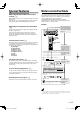
Before applying power Caution : Read this page carefully to ensure safe operation. Unpacking Units are designed for operation as follows. Unpack the unit carefully and make sure that all the accessories are present. Australia ......................................................................................AC 240 V only Europe .........................................................................................
IMPORTANT SAFETY INSTRUCTIONS Caution : Read this page carefully to ensure safe operation. Read Instructions – All the safety and operating instructions should be read before the product is operated. Retain Instructions – The safety and operating instructions should be retained for future reference. Heed Warnings – All warnings on the product and in the operating instructions should be adhered to. Follow Instructions – All operating and use instructions should be followed. 1.
Contents To ensure safety, read the items carrying this marking carefully. Before applying power ................................... 2 Safety precautions Unpacking IMPORTANT SAFETY INSTRUCTIONS ............. 3 Special features .................................................... 5 Notes on instructions ........................................... 5 Names and functions of parts ............................. 6 Setting up the system ........................................ 10 Speaker setup (Easy Setup) ......
Special p features Notes on instructions HDMI ™(High-Definition Multimedia Interface) terminal ! The operating instructions given in this manual assume that the user mainly operates the receiver using the remote control unit. When the same operation is also available on the main unit, the operating method is indicated in illustrations. The [VOLUME CONTROL], [MULTI CONTROL] and [INPUT SELECTOR] knobs on the main unit are operated by turning the knobs clockwise or counterclockwise.
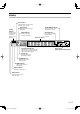
Names and functions of parts Main unit VOLUME CONTROL DOLBY DIGITAL DTS SOUND BAND STRAIGHT DECODE ACTIVE EQ SPEAKERS A/B/OFF MULTI CONTROL INPUT SELECTOR SETUP LISTEN MODE EASY SETUP MEMORY PHONES AUTO/MONO STRAIGHT INPUT MODE DECODE DIMMER VIDEO ACTIVE EQ 1 # MEMORY key (power) key Standby indicator Switch the unit ON and standby. When the unit is in standby mode, the standby indicator is lit.
Display PTY indicator Lights up when searching a radio station by program type. Speaker indicator The indicator(s) corresponding to the front speakers in use lights up. RDS indicator AUTO DETECT indicator Lights up when receiving an RDS station. Lights up when the input mode is set to "Auto". Band indicators AUTO indicator Lights up the selected broadcast band indicator. Lights up when the tuning mode is "Auto".
Names and functions of parts Remote control unit 4 PTY key fl Use for PTY search. AUTO MEMORY MEMORY ANGLE REPEAT SUBTITLE key DVD Use to operate the Kenwood DVD player.* RECEIVER 5 Numeric keys RDS DISP. AUDIO PTY SUBTITLE DIMMER Use to call up preset stations. Use to operate the Kenwood DVD player.* ACTIVE EQ BASS BOOST 6 LISTEN MODE key ¤ 7 PURE AUDIO MODE key • Use to select a listen mode. Use to switch the PURE AUDIO MODE ON/OFF.
Preparing the remote control Loading batteries œ Remove the cover. Operation When the Standby indicator is lit, the power turns ON when you press [ RECEIVER] on the remote control unit. When the power comes ON, press the key you want to operate. When operating the connected components, always press the input source key of the component you need to operate first to swith the remote control unit to the selected input source mode, and then press the keys of the corresponding operation.
Setting up the system ¤ CAUTION Do not connect the power cord to a wall outlet until all connections are completed. Speaker placement Front speaker Front speaker Make connections as shown in the following pages. When connecting the related system components, be sure to refer to the instruction manuals supplied with the components you are connecting. Subwoofer • Be sure to insert all connection cords securely.
Connecting components equipped with HDMI terminals This unit has HDMI terminals which let you enjoy high definition video such as Blu-ray discs. Audio connection (connection A or B) is necessary to output audio signal from the speakers connected to this unit. 1 Using an HDMI cable, connect the HDMI input terminal of this unit to the HDMI output terminal of a playback component. 2 Connect the audio line A (digital) or B (analog).
Setting up the system Connecting a DVD player 1 Connect the audio line : Connection A (analog) or B (digital) 2 Connect the video line and TV monitor : Connection C and F or Connection D and E VIDEO HDMI MONITOR OUT DVD/6CH IN COMPONENT VIDEO VIDEO VIDEO 2 IN DVD/6CH VIDEO 2 MONITOR IN IN OUT VIDEO 1 IN DVD/6CH VIDEO 2 MONITOR IN IN OUT VIDEO 1 IN DIGITAL IN VIDEO 1 OUT OPTICAL OPTICAL COAXIAL CD/DVD VIDEO 2 DVD/6CH AUDIO PLAY IN DVD/6CH IN SUB WOOFER CENTER MD/TAPE MD/TAPE SUB WOOFER SUR
Connecting a CD player 1 Connect the audio line : Connection A (analog) or B (digital) VIDEO HDMI MONITOR OUT DVD/6CH IN Connecting an MD player/ a cassette player 1 Connect the audio line : Connection A and B COMPONENT VIDEO VIDEO HDMI VIDEO 2 IN COMPONENT VIDEO CR DVD/6CH VIDEO 2 MONITOR IN IN OUT VIDEO 1 IN MONITOR OUT DVD/6CH IN VIDEO 2 IN DVD/6CH VIDEO 2 MONITOR IN IN OUT VIDEO 1 IN CB DIGITAL IN DIGITAL IN Y VIDEO 1 OUT OPTICAL OPTICAL COAXIAL CD/DVD VIDEO 2 DVD/6CH AUDIO PLAY IN
Setting up the system Connecting a video player 1 Connect the audio line : Connection A (analog) or B (digital) 2 Connect the video line and TV monitor : Connection C and F or Connection D and E VIDEO HDMI MONITOR OUT DVD/6CH IN COMPONENT VIDEO VIDEO VIDEO 2 IN DVD/6CH VIDEO 2 MONITOR IN IN OUT VIDEO 1 IN DVD/6CH VIDEO 2 MONITOR IN IN OUT VIDEO 1 IN DIGITAL IN VIDEO 1 OUT OPTICAL OPTICAL COAXIAL CD/DVD VIDEO 2 DVD/6CH AUDIO PLAY IN DVD/6CH IN SUB WOOFER CENTER MD/TAPE MD/TAPE SUB WOOFER
Connecting a video recorder 1 Connect the audio line : Connection A 2 Connect the video line : Connection B VIDEO HDMI MONITOR OUT DVD/6CH IN COMPONENT VIDEO VIDEO VIDEO 2 IN DVD/6CH VIDEO 2 MONITOR IN IN OUT VIDEO 1 IN DVD/6CH VIDEO 2 MONITOR IN IN OUT VIDEO 1 IN DIGITAL IN VIDEO 1 OUT OPTICAL OPTICAL COAXIAL CD/DVD VIDEO 2 DVD/6CH AUDIO PLAY IN DVD/6CH IN SUB WOOFER CENTER MD/TAPE MD/TAPE SUB WOOFER VIDEO 2 MON FRONT SPEAKERS (6–16 ) SPEAKER B SPEAKER A FM 75 VIDEO2 R L VIDEO1 R L
Setting up the system Connecting video players (COMPONENT VIDEO connection) Connecting a DVD player is described as an example. 1 Connect the audio line : See @ and make the audio connection. 2 Connect the video line and TV monitor as shown below.
Connecting the antennas The broadcast reception cannot be made unless the antennas are connected. Connect the antennas correctly as instructed below.
Setting up the system Connecting the speakers Surround Back speakers Left Right Powered subwoofer PRE OUT SUB WOOFER SURROUND BACK L/ MONO SURROUND BACK R For 6.1-channel speaker configuration, connect the surround back speaker to this terminal (with power amplifier connected in between). Select "BS MONO" in the speaker setup £.
Connecting the terminals Screw type terminal œ Strip coating. • Never short circuit the + and – speaker cords. • If the left and right speakers are connected inversely or the speaker cords are connected with reversed polarity, the sound will be unnatural with ambiguous acoustic imaging. Be sure to connect the speakers correctly. ∑ Loosen. é Insert the cord. ® Secure. Push type terminal œ Strip coating. ∑ Push the lever. é Insert the cord. ® Return the lever. English B60-5772-00_00_EN.
Setting up the system Connecting to the AV AUX jacks A component that is usually not connected to this unit, such as a portable video camera, can be connected to the [AV AUX] jacks on the front panel of this unit. VOLUME CONTROL ACTIVE EQ INPUT SELECTOR NPUT MODE PURE AUDIO MODE AV AUX VIDEO ACTIVE EQ VIDEO L-AUDIO-R L-AUDIO-R VIDEO OUT AUDIO OUT Portable video camera, game player, and etc.
Speaker setup (Easy Setup) ® Use [MULTI CONTROL ∞/5] to select your listening position. The speaker setup can be completed by simply selecting the room type and listening position. The audio will be corrected automatically according to the characteristics of the speaker system in use. If more detailed speaker settings are required, use the procedure in ™. FRONT CENTER REAR MULTI CONTROL EASY SETUP EASY SETUP † Press [EASY SETUP]. The speakers are set up as shown below.
Speaker setup (Detailed Setup) Speaker setup flow Getting into the setup mode The detailed settings below allow you to enjoy full performance of the receiver according to the environment of your listening room. The setup procedure is identical for all of the setting elements. Once you remember the following procedure, you can easily set up other setting elements. Speaker settings consist of 6 elements. Speaker Setup ("SP SETUP") £ Select whether each speaker channel is used or, if used, its size.
Speaker setup ("SP SETUP") This sets up the speakers according to the speaker system in use. Speaker setup is required every time the speaker system is changed. œ See (™) and select "SP SETUP". ∑ Use [MULTI CONTROL ∞/5] to select the subwoofer setting. Speaker Display Setting Subwoofer "SUBW ON" "SUBW OFF" With Subwoofer Without Subwoofer é Press [SETUP]. ® Repeat steps ∑ – é for the rest of the speaker setting.
Speaker setup (Detailed Setup) Adjusting the speaker level ("TEST TONE") From your usual listening position, adjust the volume output of each speaker. The output level from each speaker should be the same. Distance setting ("DISTANCE") This sets the distance from each speaker to the listening position. œ Measure the distance from the listening position to each speaker and jot down in the table below. œ See (™) and select "TEST TONE".
Crossover ("CROSS OVER") The crossover frequency is the lower limit of the bass frequencies reproduced from the speakers set to "NML" in the . The frequencies below the set crossover frequency are output from other speakers (those set to "LRG" and the subwoofer). œ See (™) and select "CROSS OVER". ∑ Use [MULTI CONTROL ∞/5] to select crossover frequency. The frequency is selected from 40, 60, 80, 100, 120, 150 and 200Hz. é Press [SETUP].
Playing music or movie Selecting the input mode Preparation Some preparatory steps are needed before starting playback. INPUT SELECTOR ¶ Operation available only on the main unit. If you have selected a component connected to the DIGITAL IN jacks (CD/DVD, VIDEO2 and DVD/6CH INPUT), make sure that the input mode setting is correct for the type of audio signal to be used. œ Use [INPUT SELECTOR] to select "CD/DVD", "VIDEO2", or "DVD/6CH". LISTEN MODE INPUT MODE ∑ Press [INPUT MODE].
Playback VOLUME CONTROL Monitoring the input source in the original sound (STRAIGHT DECODE) The signal input from a source can be output directly without any sound field effect added to it. INPUT SELECTOR AV AUX STRAIGHT DECODE œ Select the source you want to play. VOLUME /o ∑ Start playback from the selected source. é Press [STRAIGHT DECODE]. STRAIGT DECODE indicator lights up. Input source keys œ Select the source you want to play.
Playing music or movie Listening to music with PURE AUDIO MODE PURE AUDIO MODE turns the display and video circuitry (other than HDMI) off to eliminate their effects on the audio circuitry. This mode thereby makes it possible to enjoy audio with higher quality and higher fidelity to the original sound. PURE AUDIO MODE PURE AUDIO MODE œ Select the music source you want to listen to. ∑ Start playback from the selected source. é Press [PURE AUDIO MODE].
Enjoying various surround effects The below speaker placements are for 7.1 channel surround sound system which are; Listen mode This unit is equipped with listen modes that allow you to enjoy an enhanced sonic ambience with a variety of video sources. In order to obtain the optimum effect from the surround modes, make sure to input the proper speaker settings beforehand. See ¡™. • Dolby Pro Logic IIx • Neo:6 TV / SCREEN The below speaker placements are for 5.
Enjoying various surround effects Dolby Digital Dolby Pro Logic IIx Dolby Digital is a highly sophisticated and versatile audio encoding/decoding technology. Dolby Digital technology can transmit mono, stereo (two-channel), or up to 5.1-channel surround sound (discrete* multichannel audio). In 5.
DTS 96/24 DTS 96/24 made it possible to achieve a wide frequency range of over 40 kHz by increasing the sampling frequency to 96 or 88.2 kHz. Moreover, DTS 96/24’s ability of 24 bit resolution offers the same frequency band and dynamic range as 96 kHz/24 bit PCM. DTS 96/24 is, as with conventional DTS Surround, compatible with multi-channels. Therefore, sources recorded using DTS 96/24 technologies can be played in high sampling frequency, multichannel audio with ordinary DVDs and CDs.
Enjoying various surround effects Surround playback Select the listen mode according to the source being played back. "PLII MUSIC"* Pro Logic II surround Music mode "DOLBY DIGITAL" and "PRO LOGIC" "PLII GAME"* Pro Logic II surround Game mode "DOLBY DIGITAL" and "PRO LOGIC" "PRO LOGIC"* Pro Logic mode "DOLBY DIGITAL" and "PRO LOGIC" "STEREO" Stereo mode "DOLBY DIGITAL" * Available when the input signal has only 2 channels.
• Depending on the type of the signal or speaker setting, some listen modes cannot be selected. • When playback is started, the sound may be cut or interrupted before the input source is confirmed as Dolby Digital. • To enjoy Dolby Digital surround (as well as all the other listen modes) from a single component, be sure to use a Dolby Digital compatible source component.
Listening to radio broadcasts This unit can store up to 40 stations in the memory and recall them by one-touch operation. Radio stations can be classified into RDS (Radio Data System) stations and other stations. To listen to or store RDS stations in the preset memory see . Tuning (non-RDS) radio stations AUTO/MONO BAND • [MULTI CONTROL ∞/5] can also be used to select a station.
RDS Auto Memory Presetting radio stations manually This function automatically stores up to 40 RDS stations in the preset memory. In order to use the PTY function, the RDS stations must be stored in the preset memory using the RDS AUTO MEMORY function. The RDS auto memory function assigns preset numbers to RDS stations starting from preset number "1".
Listening to radio broadcasts Receiving preset stations Receiving preset stations in order (P.CALL) Numeric keys TUNER P.CALL /D TUNER œ Press [TUNER] to select tuner as the source. ∑ Enter the number of the preset station you want to receive (up to "40" preset numbers). Press the Numeric keys in the following order: For preset No. 15 : press [+10], [5] For preset No. 20 : press [+10], [+10], [0] œ Press [TUNER] to select tuner as the source. ∑ Use [P.CALL 4/¢] to select the desired station.
œ Press [PTY] to activate the PTY search mode. When an RDS broadcast is received, the program type is shown on the display. If no PTY data is available, or if the station is not an RDS station, "NONE" is displayed. Using the RDS DISP. key RDS DISP. ∑ While the "PTY" indicator is lit, use [TUNING 1/¡] to select the program type of your choice.
Recording Recording mode setting in digital audio source recording For "M-REC" mode: ¶ Operation available only on the main unit. When recording a multi-channel digital audio source, it is recommended to set up the recording mode properly to convert the digital input into the 2-channel analog output. Usually use the "A-REC" (Auto record) mode. However, some discs often produce sound skipping. The "M-REC" (Manual record) mode should be used with such a disc. ® Start playback, then start recording.
Adjusting the sound Bass Boost ¶ Operation available only on the remote control unit. The tone level can be adjusted when the input signal is a PCM or analog signal and the listen mode of this unit is set to "Stereo". Press [BASS BOOST]. MULTI CONTROL ACTIVE EQ Press the key once to select the maximum (+10) low frequency emphasis setting. TONE will automatically be turned ON. ACTIVE EQ BASS BOOST TONE MULTI CONTROL O/ To cancel Press [BASS BOOST] again.
Adjusting the sound ∑ Use the [MULTI CONTROL ∞/5] to adjust the setting as desired. Adjustment according to the playing source For detailed adjustment method, see the explanation of each item. The audio can be adjusted as desired according to the source being played. To exit the sound adjustment mode Press [SOUND]. SPEAKERS A/B/OFF Speaker level adjustment The output level from the desired speaker channels can be fine adjusted according to the properties of each disc.
Midnight mode Dimension mode ¶ Dolby Digital and DTS mode only ¶ Pro Logic IIx Music and Pro Logic II Music mode only When watching movies at night, you might not be able to raise the volume as loud as normal. Midnight mode compresses the dynamic range of previously specified heavy sound passage of the Dolby Digital and DTS mode sound track (like scenes with sudden increases in volume) to minimize the difference in volume between the scenes with heavy sound passage and scenes with normal sound passage.
Convenient functions Listening with headphones ¶ Operation available only on the main unit. œ Press [SPEAKERS A/B/OFF] so that the speaker indicator goes off. Make sure the "SP" indicator is turned off. SPEAKERS A/B/OFF DIMMER VOLUME CONTROL DIMMER If you turn off all of the speakers when in surround mode, the surround mode will be canceled as well, resulting in stereo playback. ∑ Connect headphones to the PHONES jack.
Remote control operations for Kenwood DVD players The remote control of this unit can control Kenwood DVD players directly without using the remote control supplied with the DVD player.
Troubleshooting Troubles are not always due to malfunction or failure of the system. In case of a trouble, check the following tables before calling for service. Amplifier Symptom No sound from the speakers. Cause The speaker cords are disconnected. VOLUME is set to the minimum position. MUTE is ON. The SPEAKERS switches are set to OFF. No sound from the speakers when playing the source connected with HDMI connection. The standby indicator blinks and sound is not output.
Tuner Symptom Radio stations cannot be received. Cause Remedy No antenna is connected. Connect an antenna. & The broadcast band is not set properly. Set the broadcast band properly. › The frequency of the desired station is not tuned. Tune the frequency of the desired station. › Install the outdoor antenna away from the road. Turn off the power to the appliance. Install the unit farther away from the TV. Interference Noise due to ignition of an automobile.
Troubleshooting Resetting the Microcomputer In regard to contact cleaner The microcomputer may malfunction (unit cannot be operated, or shows an erroneous display) if the power cord is unplugged while the power is ON, or due to some other external factor. If this happens, execute the following procedure to reset the microcomputer and return the unit to its normal operating condition. Do not use contact cleaners because it could cause a malfunction.
Specifications AUDIO section VIDEO section Rated output power during STEREO operation (63 Hz – 12.5 kHz, 0.7% T.H.D., at 6 Ω).............100 W + 100 W Effective output power during STEREO operation RMS (1 kHz, 10% T.H.D., at 6 Ω) ......................... 130 W + 130 W Effective power output during SURROUND operation FRONT (1 kHz, 0.7 % T.H.D. at 6 Ω one channel driven) .. 100 W + 100 W (1 kHz, 10 % T.H.D. at 6 Ω one channel driven) ... 130 W + 130 W CENTER (1 kHz, 0.7 % T.H.D.
For your records Record the serial number, found on the back of the unit, in the spaces designated on the warranty card, and in the space provided below. Refer to the model and serial numbers whenever you call upon your dealer for information or service on this product. Model B60-5772-00_00_EN.indd 48 Serial Number 08.7.