INSTRUCTION MANUAL MODE D’EMPLOI MANUAL DE INSTRUCCIONES MANUAL DI ISTRUZIONI BEDIENUNGSANLEITUNG GEBRUIKSAANWIJZING TK-2140/ TK-3140 VHF FM TRANSCEIVER/ UHF FM TRANSCEIVER ÉMETTEUR-RÉCEPTEUR FM VHF/ ÉMETTEUR-RÉCEPTEUR FM UHF TRANSCEPTOR DE FM VHF/ TRANSCEPTOR DE FM UHF RICETRASMETTITORE FM VHF/ RICETRASMETTITORE FM UHF VHF-FM-TRANSCEIVER/ UHF-FM-TRANSCEIVER VHF FM ZENDONTVANGER/ UHF FM ZENDONTVANGER © B62-1479-10 (E,E3) 09 08 07 06 05 04 03 02 01
VHF FM TRANSCEIVER/ UHF FM TRANSCEIVER INSTRUCTION MANUAL ENGLISH TK-2140/ TK-3140
THANK YOU We are grateful you chose KENWOOD for your land mobile radio applications. We believe this easy-to-use transceiver will provide dependable communications to keep personnel operating at peak efficiency. KENWOOD transceivers incorporate the latest in advanced technology. As a result, we feel strongly that you will be pleased with the quality and features of this product.
CONTENTS UNPACKING AND CHECKING EQUIPMENT .............................. 1 SUPPLIED ACCESSORIES .................................................... 1 PREPARATION .............................................................. 2 BATTERY PACK PRECAUTIONS ............................................... 2 INSTALLING/ REMOVING THE (OPTIONAL) RECHARGEABLE BATTERY PACK OR ALKALINE BATTERY CASE .......................................... 7 INSTALLING/ REMOVING ALKALINE BATTERIES .................................
UNPACKING AND CHECKING EQUIPMENT Note: The following unpacking instructions are for use by your KENWOOD dealer, an authorized KENWOOD service facility, or the factory. Carefully unpack the transceiver. We recommend that you identify the items listed in the following table before discarding the packing material. If any items are missing or have been damaged during shipment, file a claim with the carrier immediately.
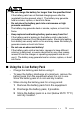
PREPARATION BATTERY PACK PRECAUTIONS ◆ Do not recharge the battery pack if it is already fully charged. Doing so may cause the life of the battery pack to shorten or the battery pack may be damaged. ◆ After recharging the battery pack, disconnect it from the charger. If the charger power is reset (turned ON after being turned OFF), recharging will start again and the battery pack will become overcharged. ◆ Do not use the transceiver while charging the battery pack.
• • • • • • • Do not incinerate or apply heat to the battery! If the insulator is melted, the gas release vent or safety function is damaged, or the electrolyte is ignited, the battery may generate heat or smoke, rupture, or burst into flame.
• • • • • Do not use the battery pack if it is damaged in any way! The battery may generate heat or smoke, rupture, or burst into flame. Do not solder directly onto the battery! If the insulator is melted or the gas release vent or safety function is damaged, the battery may generate heat or smoke, rupture, or burst into flame. Do not reverse the battery polarity (and terminals)! When charging a reversed battery, an abnormal chemical reaction may occur.
• Do not charge the battery for longer than the specified time! If the battery pack has not finished charging even after the regulated time has passed, stop it. The battery may generate heat or smoke, rupture, or burst into flame. Do not place the battery pack into a microwave or high pressure container! The battery may generate heat or smoke, rupture, or burst into flame.
■ Characteristics of the Li-ion Battery Pack • • • • • As the battery pack is charged and discharged repeatedly, the battery capacity decreases. Even if the battery pack is unused, the battery pack degrades. It takes a longer time to charge the battery pack in cooler areas. The life of battery pack is shortened when it is charged and discharged in hotter areas. When the battery pack is stored in a hot location, the battery pack degrades quicker.
INSTALLING/ REMOVING THE (OPTIONAL) RECHARGEABLE BATTERY PACK OR ALKALINE BATTERY CASE 1 Match the guides of the battery pack with the corresponding grooves on the upper rear of the transceiver, then firmly press the battery pack to lock it in place. 2 Flip the safety catch into place to prevent accidentally pressing the release latch and removing the battery. 3 To remove the battery pack, lift the safety catch, press the release latch, then pull the battery pack away from the transceiver.
INSTALLING/ REMOVING ALKALINE BATTERIES ◆ Do not install batteries in a hazardous environment where sparks could cause an explosion. ◆ Never discard old batteries in fire; extremely high temperatures can cause batteries to explode. ◆ Do not short circuit the battery case terminals. ◆ Do not use commercially available rechargeable or manganese batteries. Note: ◆ If you do not plan to use the transceiver for a long period, remove the batteries from the battery case.
INSTALLING THE ANTENNA Screw the antenna into the connector on the top of the transceiver by holding the antenna at its base and turning it clockwise until secure. INSTALLING THE BELT CLIP Note: When first installing the belt clip, you must remove the battery pack from the rear of the transceiver. 1 Remove the two screws from the rear of the transceiver, then remove the small, plastic black covering that was held in place. 2 Insert the belt clip mount into the space on the rear of the transceiver.
INSTALLING THE COVER OVER THE UNIVERSAL CONNECTOR If you are not using the optional KMC-25 speaker/ microphone, install the cover over the universal connector using the supplied 4 x 6 mm dressed screw. INSTALLING THE (OPTIONAL KMC-25) SPEAKER/ MICROPHONE 1 Insert the guide of the speaker/ microphone connector into the groove of the universal connector. 2 Secure the connector in place using the attached screw.
GETTING ACQUAINTED 1 2 4 3 5 6 7 11 12 13 14 8 9 10 Microphone 15 Speaker q Antenna connector Connect the antenna here. w Rotary encoder Rotate this encoder to activate its programmable function: Channel Up/ Down (default) or Group Up/ Down. For further details, contact your dealer. e Power switch/ Volume control Turn clockwise to switch ON the transceiver. Rotate to adjust the volume. Turn counterclockwise fully to switch OFF the transceiver.
r LED indicator This LED lights red during transmission and green while receiving a signal. During Selective Call Alert, the LED flashes orange. If programmed by your dealer, when the battery pack power is low, the LED flashes red during transmission. Replace or recharge the battery pack at this time. Note: While operating the transceiver using a Li-ion battery pack, the battery low indication time may be much shorter than when using other battery packs.
!0 Side 2 key Press to activate its auxiliary function {page 15}. The default setting of this key is Call 1 for the 5-Tone model. The DTMF/2-Tone/DMS model has no default setting. !1 S key Press to activate its auxiliary function {page 15}. The default setting of this key is Selcall Entry for the 5-Tone model. The DTMF/2-Tone/DMS model has no default setting. !2 A key Press to activate its auxiliary function {page 15}. The default setting of this key is Receive Entry for the 5-Tone model.
DISPLAY Indicator Description Displays the group and channel number as well as various dealer programmable settings. Appears when the Priority Channel is selected. Appears when the key programmed as Monitor is pressed. This icon is not used on this transceiver. Appears when performing Scan. Appears when the key programmed as RF Power Low is pressed. This icon is not used on this transceiver. Appears when a message is stored in the queue memory. Flashes when you receive a new message.
PROGRAMMABLE AUXILIARY FUNCTIONS Keys w, t, and o to !4 {pages 11 to 13} can be programmed with the auxiliary functions listed in the following table. The keys can only be programmed with functions, depending on the model purchased. Please contact your dealer for further details on these functions.
DTMF/2-Tone/ DMS Model 5-Tone Model Low Power Monitor Monitor Momentary None Operator Selectable Tone Queue Radio Password Receive Entry Scan Scan Delete/Add Selcall Entry Selcall List Selcall + Status Entry Selcall + Status List Shift Single Tone (1750 Hz) Single Tone (2135 Hz) Squelch Level Squelch Momentary Squelch Off Status Entry Status List Yes Yes Yes Yes Yes Yes Yes No Yes Yes No Yes No Yes Yes Yes Yes Yes Yes Yes No No Yes Yes Yes Yes Yes Yes Yes Yes Yes Yes Yes Yes Yes Yes Yes Yes Yes Yes Yes
OPERATING BASICS SWITCHING POWER ON/ OFF Turn the Power switch/ Volume control clockwise to switch the transceiver ON. • If the Radio Password function is programmed, “LOCK 1” will appear on the display when the power is turned ON. To unlock the transceiver, enter the password, then press the Side 2 key. If you enter the wrong password, an error tone sounds and the transceiver remains locked. The password can contain a maximum of 6 digits.
MAKING A CALL 1 Select the desired group and channel. 2 Press the Monitor key to check whether or not the channel is free. • • You must use the key programmed with either Monitor or Monitor Momentary. If the channel is busy, wait until it becomes free. 3 Press and hold the PTT switch and speak into the microphone. Release the PTT switch to receive. • For best sound quality at the receiving station, hold the microphone approximately 3 ~ 4 cm (1.5 inches) from your mouth.
SCAN If the Scan function is programmed, groups or channels can be scanned by pressing the key programmed as Scan. Scan can be used as either Single Scan or Multi Scan. Single Scan monitors only the channels of a single group. Multi Scan monitors all channels of every group. When the Scan key is pressed, the SCN indicator and “-SCAN-” or the revert group/ channel number appear on the display and scanning starts. When a call is received, scanning stops and the group and channel digits appear.
SCAN LOCKOUT If a programmable auxiliary key is programmed with Scan Del/Add, each channel can be locked out of the scan sequence manually. The add indicator ( ▼ ) will no longer appear on the display when the selected channel is locked out. SCAN REVERT You can select a revert channel using the Channel keys (or encoder). Six types of Scan Reverts which can be programmed by your dealer are available: • Last Called: The last channel received is assigned as the new revert channel.
SIGNALLING DTMF SIGNALLING Your dealer can program a group with a DTMF signalling code. When you receive a call with a code that matches yours, the signalling indicator will flash and a tone will sound. Squelch opens and you will hear the call. Squelch will close when you receive a call with a code that matches your signalling reset code. When making a call on a group programmed with a DTMF signalling code, the signalling indicator will light and the squelch will open.
5-TONE SIGNALLING 5-Tone Signalling is either activated or deactivated by your dealer. 5-Tone Signalling only opens the squelch when the transceiver receives five tones corresponding to those set up in the transceiver. When the squelch opens, you will be able to hear the caller without any further action. After a correct 5-Tone signal is received and the squelch opens, pressing the key programmed as Monitor will cancel the connection.
DMS: ALPHANUMERIC 2-WAY PAGING FUNCTION DMS (Digital Message System) is an Alphanumeric 2-way Paging Function, and is a protocol owned by KENWOOD Corporation. DMS enables a variety of paging functions on your transceiver, some of which depend on dealer programming.
SELCALL (SELECTIVE CALLING) A Selcall is a voice call to a particular station or to a group of stations. ■ Transmitting 1 Select your desired group and channel. 2 Press the key programmed as Selcall List to enter Selcall Mode. 3 Use the encoder to select the ID of the station you want to call. 4 Press the PTT switch and begin your conversation. ■ Receiving An alert tone will sound, the transceiver will automatically enter Selcall Mode, and the calling station’s ID will appear when a Selcall is received.
STATUS MESSAGE You can send and receive 2-digit Status messages (10 ~ 79) which may be decided in your talk group. Messages can contain up to 16 alphanumeric characters. A maximum of 15 received messages can be stored in the queue memory of your transceiver. These saved messages can be reviewed after reception. If the queue memory is full, the oldest message will be erased when a new message is received. The mail icon ( ) lights when a message is stored in the queue memory.
Press any key or wait until the pre-programmed timer expires to return to Normal Operation Mode. ■ Reviewing the Messages in the Queue Memory 1 Press the key programmed as Queue to enter Queue Mode. • Depending on how your dealer has set up your transceiver, either the last received message or the first received message is displayed along with the message number. 2 Use the encoder to select the message you want to view (if more than one message is stored in the queue memory).
AUDIBLE USER FEEDBACK TONES The transceiver emits various tones to indicate the transceiver’s operating status.