
Installation Guide


7
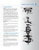
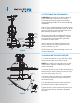
Fig. 13
Step 2. Motor to Receiver Electrical
Connections: (Fig. 13)
Connect the black wire from the fan to the
black wire marked "TO MOTOR L" on the
receiver.
Connect the white wire from the fan to the
white wire marked "TO MOTOR N" on the
receiver.
Connect the blue wire from the fan to the blue
wire marked "FOR LIGHT" on the receiver.
Secure each set of wire connections with the
plastic wire nuts provided in the parts bag.
Step 3. (Fig. 13) Receiver to House Supply
Wires Electrical Connections:
Connect the black (hot) wire from the ceiling to
the black wire marked "AC in L" from the
receiver.
Connect the white(neutral) wire from the
ceiling to the white wire marked "AC in N" from
the Receiver.
Secure the wire connections with the plastic
wire nuts provided.
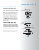
Step 4. (Fig. 13) If your outlet box has a
ground wire (green or bare copper) connect it
to the fan ground wires; otherwise connect the
hanging bracket ground wire to the mounting
bracket. Secure the wire connection with a
plastic nut provided. After connecting the
wires, spread them apart so that the green
and white wires are on one side of the outlet
box and black and blue wires are on the other
side. Carefully tuck the wire connections up
into the outlet box.
Note: Fan must be installed at a maximum
distance of 30 feet from the CoolTouch™
Remote Transmitter for optimal signal
transmission between the transmitter and the
fan's receiving unit.
White (neutral)
White (neutral)
Green or bare
copper (ground)
White ("AC IN N")
White ("to motor N")
Ground
(green)
(Connect to
ground wire on
hanger bracket
if no house
ground wire
exists.)
Outlet box
Black (hot)
Black ("AC IN L")
Black ("to motor L")
Receiver
Blue (for light)
Blue (for light)
Black (motor)