
Instruction Sheet

1) Fixture can be assembled with the glass pointing up or down. Determine desired
direction.
2) Lay fixture body on flat surface with sockets facing direction desired when
installed.
3) Pull supply wire up through center stem.
4) Screw center stem onto coupling on top of fixture body.
5) Pass bottom trim over threaded pipe on bottom of fixture body.
6) Screw finial onto end of threaded pipe.
7) Turn off power.
8) Take threaded pipe from parts bag and screw in screw collar loop a minimum
of 6 mm (1/4”). Lock into place with hexnut.
9) Run another hexnut down threaded pipe almost touching first hexnut. Now screw
threaded pipe into mounting strap. Mounting strap must be positioned with
extruded thread faced into outlet box. Threaded pipe must protrude out the back
of mounting strap. Connect mounting strap to outlet box.
10) Unscrew the threaded ring from screw collar loop. Take canopy and pass over
screw collar loop. Approximately one half of the screw collar loop exterior threads
should be exposed. Adjust screw collar loop by turning assembly up or down in
mounting strap. Remove canopy.
11) After desired position is found, tighten top hexnut up against the bottom of the
mounting strap.
12) Slip canopy over screw collar loop and thread on threaded ring. Attach chain
(with fixture connected) to bottom of screw collar loop. Unscrew threaded ring,
let canopy and threaded ring slip down.
13) Weave electrical wire and ground wire through chain links no more than 3 inches
apart. Pass wire through threaded ring, canopy, screw collar loop, threaded pipe
and into outlet box.
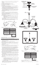
14) Grounding instructions: (See Illus. A or B).
A) On fixtures where mounting strap is provided with a hole and two raised
dimples. Wrap ground wire from outlet box around green ground screw,
and thread into hole.
B) On fixtures where a cupped washer is provided. Attach ground wire from
outlet box under cupped washer and green ground screw, and thread
into mounting strap.
If fixture is provided with ground wire. Connect fixture ground wire to outlet box
ground wire with wire connector (not provided.) after following the above steps.
Never connect ground wire to black or white power supply wires.
15) Make wire connections (connectors not provided). Reference chart below for
correct connections and wire accordingly.
16) Raise canopy to ceiling.
17) Secure canopy in place by tightening threaded ring onto screw collar loop.
18) Slip glass over sockets and secure in place with socket rings.
1) Se puede montar el artefacto con el vidrio apuntando hacia arriba o abajo.
Determine la dirección deseada.
2) Ponga el cuerpo del artefacto con los casquillos mirando en la dirección deseada
al quedar instalado.
3) Estire el alambre de alimentación a través del vástago central.
4) Atornille el vástago central en el acomplamiento, en el tope del cuerpo del artefacto.
5) Resbale la guarnición inferior encima del tubo roscado, en la parte inferior del
cuerpo del artefacto.
6) Atornille el capuchón al extremo del tubo roscado en la parte inferior del cuerpo
del artefacto.
7) Apague la alimentación eléctrica.
8) Tome el tubo roscado de la bolsa de piezas y atornille en el ojal de collar roscado
un mínimo de 6 mm. (1/4”). Inmovilice en el lugar con la tuerca hexagonal.
9) Instale otra tuerca hexagonal abajo del tubo roscado, casi tocando la primera
tuerca hexagonal. Ahora atornille el tubo roscado en la abrazadera de montaje. La
abrazadera de montaje se debe colocar con la rosca extruída mirando hacia
la caja de salida. El tubo roscado debe sobresalir atrás de la abrazadera de
montaje. Conecte la abrazadera de montaje a la caja de salida.
10) Destornille el anillo roscado del ojal de collar roscado. Tome el escudete y pase
sobre el ojal de collar roscado. Aproximadamente la mitad de las roscas exteriores
del ojal de collar roscado deben estar expuestas. Ajuste el ojal del collar roscado
girando el conjunto arriba o abajo en la abrazadera de montaje. Quite el escudete.
11) Después de encontrar la posición deseada, apriete la tuerca hexagonal superior
contra la inferior de la abrazadera de montaje.
12) Resbale el escudete sobre el ojal de collar roscado y rosque en el anillo roscado.
Acople la cadena (con el artefacto conectado) a la parte inferior del ojal de collar
roscado. Destornille el anillo roscado, deje que el escudete y el anillo roscado
resbalen hacia abajo.
13) Pase el alambre eléctrico y el alambre de tierra a través de los eslabones de la
cadena, con una separación de 3 pulgadas máxima. Pase el alambre a través del
anillo roscado, del escudete, del ojal de collar roscado, del tubo roscado y en la
caja de salida.
14) Instrucciones de conexión a tierra solamente para los Estados Unidos. (Vea la
ilustracion A o B).
A) En las lámparas que tienen el fleje, de montaje con un agujero y dos hoyue
los realzados. Enrollar el alambre a tierra de la caja tomacorriente alrededor
del tornillo verde y pasarlo por el aquiero.
B) En las lámparas con una arandela acopada. Fijar el alambre a tierra de la
caja tomacorriente del ajo de la arandela acoada y tornillo verde, y paser
por el fleje de montaje.
Si la lámpara viene con alambre a tierra. Conecter el alambre a tierra de la lámpara
al alambre a tierra de la caja tomacorriente con un conector de alambres (no
incluido) espués de seguir los pasos anteriores. Nunca conectar el alambra a
tierra a los alambres eléctros negro o blanco.
GREEN GROUND
SCREW
CUPPED
WASHER
A
B
OUTLET BOX
GROUND
FIXTURE
GROUND
DIMPLES
WIRE CONNECTOR
(NOT PROVIDED)
OUTLET BOX
GROUND
GREEN GROUND
SCREW
FIXTURE
GROUND
Connect Black or
Red Supply Wire to:
Connect
White Supply Wire to:
Black White
*Parallel cord (round & smooth) *Parallel cord (square & ridged)
Clear, Brown, Gold or Black
without tracer
Clear, Brown, Gold or Black
with tracer
Insulated wire (other than green)
with copper conductor
Insulated wire (other than green)
with silver conductor
*Note: When parallel wires (SPT I & SPT II)
are used. The neutral wire is square shaped
or ridged and the other wire will be round in
shape or smooth (see illus.)
Neutral Wire
Date Issued: 10/12/07
IS-2076-US
GLASS
VIDRIO
15) Haga les conexiones de los alambres (no se proveen los connectores.) La tabla
de referencia de abajo indica las conexiones correctas y los alambres correspondientes.
16) Levante el escudete al cielo raso.
17) Sujete el escudete en el lugar apretando el anillo roscado en el ojal de collar
roscado.
18) Resbale el vidrio sobre los casquillo y sujete en el lugar con los anillo del casquillo.
ARANDELA
CONCAVA
A
B
TIERRA DE LA
CAJA DE SALIDA
TORNILLO DE TIERRA,
VERDE
DEPRESIONES
TIERRA
ARTEFACTO
CONECTOR DE ALAMBRE
(NO SE PROVEE)
TIERRA DE LA
CAJA DE SALIDA
TORNILLO DE TIERRA,
VERDE
TIERRA
ARTEFACTO
Conectar el alambre de
suministro negro o rojo al
Conectar el alambre de
suministro blanco al
Negro Blanco
*Cordon paralelo (redondo y liso)
*Cordon paralelo (cuadrado y estriado)
Claro, marrón, amarillio o negro
sin hebra identificadora
Claro, marrón, amarillio o negro
con hebra identificadora
Alambre aislado (diferente del verde)
con conductor de cobre
Alambre aislado (diferente del
verde) con conductor de plata
*Nota: Cuando se utiliza alambre paralelo
(SPT I y SPT II). El alambre neutro es de forma
cuadrada o estriada y el otro alambre será de
forma redonda o lisa. (Vea la ilustracíón).
Hilo Neutral
MOUNTING STRAP
ABRAZADERA DE
MONTAJE
HEXNUT
TUERCA
HEXAGONAL
THREADED PIPE
TUBO ROSCADO
SCREW COLLAR LOOP
OJAL DE COLLAR
ROSCADO
CANOPY
ESCUDETE
THREADED RING
ANILLO ROSCADO
LOOP
LAZO
SOCKET RING
ANILLO DEL
CASQUILLO
FIXTURE BODY
CUERPO DEL
ARTEFACTO
FINIAL
CAPUCHON
BOTTOM TRIM
GUARNICIÓN INFERIOR
THREADED PIPE
TUBO ROSCADO
FIXTURE WITH GLASS IN UPWARD POSITION