A Kichler ® Décor™ ceiling fan Designed to coordinate with a popular Kichler Lighting collection. TM Looks permanent, but goes wherever you go! U.S. Patent Pending Kichler® Lighting 7711 East Pleasant Valley Road P.O. Box 318010 Cleveland, Ohio 44131-8010 Customer Service 866.558.
1 1. SAFETY RULES 1. To reduce the risk of electric shock, insure electricity has been turned off at the circuit breaker or fuse box before beginning. 2. All wiring must be in accordance with the National Electrical Code and local electrical codes. Electrical installation should be performed by a qualified licensed electrician. 10. Do not use water or detergents when cleaning the fan or fan blades. A dry dust cloth or lightly dampened cloth will be suitable for most cleaning. 3.
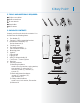
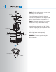
Kittery Point TM 2 2. TOOLS AND MATERIALS REQUIRED Philips screw driver Blade screw driver 11 mm wrench Step ladder Wire cutters 3. PACKAGE CONTENTS Unpack your fan and check the contents. You should have the following items: j b a. b. c. Fan blades (5) Canopy & Ceiling mounting bracket Ball/downrod assembly (1) & extra downrod (1) d. Coupling cover e. Fan motor assembly f. Set of blade brackets (5) g. Mounting plate h. Light kit i. Glass shade j. Light kit clip k. 40W T3 halogen bulbs (4) l.
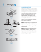
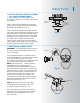
3 4. MOUNTING OPTIONS If there isn't an existing UL (cUL for Canadian Installation) listed mounting box, then read the following instructions. Disconnect the power by removing fuses or turning off circuit breakers. Outlet box Fig. 1 Secure the outlet box directly to the building structure. Use appropriate fasteners and building materials. The outlet box and its support must be able to fully support the moving weight of the fan (at least 50 lbs). Do not use plastic outlet boxes.
Kittery Point TM 5. HANGING THE FAN REMEMBER to turn off the power before you begin. To properly install your ceiling fan, follow the steps below. Step 1. Remove the decorative canopy bottom cover from the canopy by turning the cover counter clockwise. (Fig. 5) Step 2. Remove the hanger bracket from the canopy by loosening the two screws on the bottom of the hanging bracket. Turn the canopy counterclockwise and remove. (Fig.
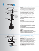
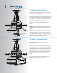
5 Hanger ball Step 8. Slip the coupling cover, canopy cover and canopy onto the downrod. Downrod Canopy Canopy cover Step 9. Lift the motor assembly into position and place the hanger ball into the ceiling mounting bracket. Screws Coupling cover Thread the hanger ball onto the downrod, insert the cross pin through the downrod and tighten. Now tighten the set screw. (Fig. 9) Set screws Rotate the entire assembly until the "Check Tab" has dropped into the "Registration Slot" and seats firmly. (Fig.
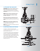
Kittery Point TM 6. INSTALLATION OF SAFETY SUPPORT (for Canadian Installation ONLY) A safety support cable is provided to help prevent the ceiling fan from falling, please install it as follows. Ceiling mounting bracket Attach safety cable to ceiling joist with screw and washer Step 1. Attach the provided wood screw and washer to the ceiling joist next to the mounting bracket but do not tighten. (Fig. 11) Step 2.
7 Outlet box White (neutral) Black (hot) Green or bare copper (ground) Black ("AC IN L") White ("AC IN N") Receiver White ("to motor N") Black ("to motor L") Blue (for light) Blue (for light) Black (motor) Ground (Connect to (green) ground wire on hanger bracket if no house ground wire exists.) White (neutral) Fig. 14 Step 2. Motor to Receiver Electrical Connections: (Fig. 14) Connect the black wire from the fan to the black wire marked "TO MOTOR L" on the receiver.
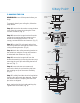
Kittery Point TM 8 9. ATTACHING THE FAN BLADES CAUTION: Remove the five rubber shipping blocks attached to the face of the motor. These blocks keep the motor from shifting during shipping and MUST be removed during installation. Step 1. Place a blade on the blade bracket. Attach the blade to the bracket using the screws, metal washers and fiber washers provided. (Fig. 16) Screws Washers Fiber washers Make sure the blade is straight when set on the blade bracket.
9 11. INSTALLING THE LIGHT KIT Step 1. Loosen the three mounting screws on the inside of the light fixture. Hold the light plate close to the light fixture and connect the white wires from the light plate and the fan. Follow the same procedure with the black wire connectors. (Fig. 18) Tuck the connections neatly into the light fixture. NOTE: Be careful not to pinch the light plate wires between the light plate and the light fixture. Wire connectors Light fixture Mounting screws Light plate Fig.
Kittery Point TM 13. INSTALLING THE BATTERY Remove the battery compartment cover on the back of the CoolTouch™ Transmitter and insert both batteries provided. Make sure the + sign is facing up. Take care during this procedure NOT TO move the frequency dip switches inside this compartment. The settings MUST remain the same as the settings on the receiver for proper communication with the control system. It's a good idea to remove these batteries if your fan is not used for extend periods of time, (months).
11 Speed settings for warm or cool weather depend on factors such as the room size. Ceiling height, number of fans and so on. Warm Weather Operation: Forward (counter clockwise) A downward airflow creates a cooling effect as shown in Fig. 22. This allows you to set your air conditioner on a warmer setting without affecting your general comfort. Fig. 22 Fig. 23 Cool Weather Operation: Reverse (clockwise). An upward airflow moves warm air off the ceiling areas as shown in Fig. 23.
Kittery Point TM 15. INSTALLING THE COOLTOUCH™ CONTROL SYSTEM WALL PLATE Outlet box Switch Select a location to install your CoolTouch™ Control System Transmitter. You can replace an existing wall switch or, install the transmitter on ANY flat surface. Wall plate Option 1: Install the control system using an existing wall switch outlet box. Make sure the electrical power is TURNED OFF at the main panel before continuing. Step 1.
13 17. TROUBLESHOOTING Problem Solution Fan will not start. 1. Check circuit fuses or breakers. 2. Check all electrical connections to insure proper contact. CAUTION: Make sure the main power is OFF when checking any electrical connection. 3. Make sure the batteries are installed properly. Positive (+) side facing out. 4. Check to make sure the batteries are installed properly. (Positive + side facing out) 5. Check to make sure the batteries are not dead. Fan sounds noisy. 1.