
Installation Guide


7
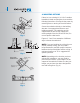
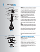
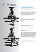
Fig. 15
Outlet box
Hanger
bracket
Canopy
Canopy cover
Screws
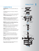
Fig. 14
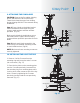
Step 1. Tuck all the connections neatly into
the ceiling outlet box.
MAKE SURE the Black Antenna wire on the
receiver remains free from all other wires.
Step 2. Slide the canopy up to ceiling and over
the two screws on hanger bracket. Rotate
canopy clockwise, next, while holding the
canopy with one hand, slide the canopy cover
over the screws and rotate clockwise until
tight. NOTE: Adjust the canopy screws as
necessary until the canopy and canopy cover
are snug. (Fig.15)
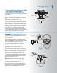
Step 2. Motor to Receiver Electrical Connections:
(Fig. 14)
Connect the black wire from the fan to the black
wire marked "TO MOTOR L" on the receiver.
Connect the white wire from the fan to the white
wire marked "TO MOTOR N" on the receiver.
Connect the blue wire from the fan to the blue
wire marked "FOR LIGHT" on the receiver.
Secure each set of wire connections with the
plastic wire nuts provided in the parts bag.
Step 3. Receiver to Supply Wires Electrical
Connections: (Fig. 14)
Connect the black (load) wire from the ceiling
outlet box to the black wire marked "AC in L" on
the receiver.
Connect the white (neutral) wire from the ceiling
outlet box to the white wire marked "AC in N" on
the receiver.
Secure each set of electrical connections with
with the plastic wire nuts provided in the parts
bag.
Step 4. Connect the ground wire (green or bare
copper) from the outlet box to the ground wire on
the ceiling mounting bracket and the ground wire
from the ceiling fan.
After making all connections, separate the white
and green wire connections to one side and the
black wire connections to the other side of the
outlet box.
Note: Fan must be installed at a maximum
distance of 30 feet from the CoolTouch
™
Remote
Transmitter for optimal signal transmission
between the transmitter and the fan's receiving
unit.
White (neutral)
White (neutral)
Green or bare
copper (ground)
White ("AC IN N")
White ("to motor N")
Ground
(green)
(Connect to
ground wire on
hanger bracket
if no house
ground wire
exists.)
Outlet box
Black (hot)
Black ("AC IN L")
Black ("to motor L")
Receiver
Blue (for light)
Blue (for light)
Black (motor)
8. FINISHING THE INSTALLATION