Kichler® Lighting 7711 East Pleasant Valley Road P.O. Box 318010 Cleveland, Ohio 44131-8010 Customer Service 866.558.
1 1. SAFETY RULES 1. To reduce the risk of electric shock, insure electricity has been turned off at the circuit breaker or fuse box before beginning. 2. All wiring must be in accordance with the National Electrical Code and local electrical codes. Electrical installation should be performed by a qualified licensed electrician. 3. WARNING: Not suitable for use with solid-state speed controls. 4.
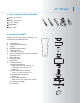
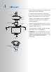
42" Bowen 2. TOOLS AND MATERIALS REQUIRED Philips screw driver Blade screw driver 11 mm wrench Step ladder Wire cutters 3. PACKAGE CONTENTS Unpack your fan and check the contents. You should have the following items: a. b. c. d. e. f. g. h. i. j. k.
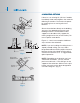
3 4. MOUNTING OPTIONS If there isn't an existing UL (cUL for Canadian Installation) listed mounting box, then read the following instructions. Disconnect the power by removing fuses or turning off circuit breakers. Outlet box Fig. 1 Secure the outlet box directly to the building structure. Use appropriate fasteners and building materials. The outlet box and its support must be able to fully support the moving weight of the fan (at least 50 lbs). Do not use plastic outlet boxes.
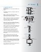
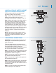
42" Bowen 5. HANGING THE FAN Hanger bracket REMEMBER to turn off the power before you begin. Ceiling canopy To properly install your ceiling fan, follow the steps below. Step 1. Remove the decorative canopy bottom cover from the canopy by turning the cover counter clockwise. (Fig. 5) Step 2. Remove the ceiling mounting bracket from the canopy by removing (and save one of the two screws. Loosen the remaining screw by a half turn. (Fig. 5) Canopy cover Fig.
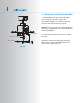
5 Step 8. Slip the coupling cover, canopy cover and canopy onto the downrod. Thread the hanger ball onto the downrod, insert the cross pin through the downrod and tighten. Now tighten the set screw. (Fig. 9) Downrod Canopy Canopy cover Coupling cover Set screws Hitch pin Retaining clip Fig. 9 Registration slot Fig. 10 Step 9. Lift the motor assembly into position and place the hanger ball into the ceiling mounting bracket.
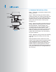
42" Bowen 6. INSTALLATION OF SAFETY SUPPORT (required for Canadian installation ONLY) A safety support cable is provided to help prevent the ceiling fan from falling. Step 1. Attach the provided wood screw and washers to the ceiling joist next to the mounting bracket but do not tighten. (Fig. 11) Ceiling mounting bracket Attach safety cable to ceiling joist with screw and washer Step 2.
7 8. FINISHING THE INSTALLATION Step 1. Tuck all the connections neatly into the ceiling outlet box. Outlet box Ceiling mounting bracket Screws Canopy Screws Canopy cover Fig. 13 Step 2. Slide the canopy up to the mounting bracket and place one of the key hole slots over the mounting screw on the mounting bracket. Rotate the canopy until the screw head locks in place at the narrow section of the key hole. See figure 13. Step 3.
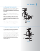
42" Bowen 9. ATTACHING THE FAN BLADES CAUTION: Remove the five rubber shipping blocks attached to the face of the motor. These blocks keep the motor from shifting during shipping and MUST be removed during installation. Step 1. Attach a blade to a blade bracket using the screws and fiber washers provided. (Fig. 14) Screws Make sure the blade is straight when set on the blade bracket. Tighten each mounting screw until the fiber washer is slightly compressed. Repeat this procedure for each blade.
9 11. INSTALLING THE SWITCH HOUSING 1. While holding the switch housing under your ceiling fan, push the square wire connectors together. One from the fan and one from the switch housing. (Fig.16) NOTE: These connectors are color coded and will ONLY engage when the colored strips are matched (aligned). Mounting plate Square wire connectors Switch housing Screws Fig. 16 2. Carefully push all the wires into the switch housing. Attach the switch housing to the mounting plate with the screws provided.
42" Bowen 12. OPERATING INSTRUCTIONS Turn the power on and check the operation of your ceiling fan. The pull chain controls the 3 speeds of your ceiling fan. 1 pull = High, 2 pulls = Medium, 3 pulls = Low and the 4th pull turns the motor off. The Black Slide Switch on the side of the switch housing controls the direction of the blades "Forward and Reverse" Fig. 17 Warm weather - Forward (counter clockwise) A downward airflow creates a cooling effect as shown in Fig. 17.
11 13. TROUBLESHOOTING Problem Solution Fan will not start. 1. Check circuit fuses or breakers. 2. Check all electrical connections to insure proper contact. CAUTION: Make sure the main power is OFF when checking any electrical connection. Fan sounds noisy. 1. Make sure all motor housing screws are snug. 2. Make sure the screws that attach the fan blade brackets to the motor are tight. 3. Make sure wire nut connections are not rubbing against each other or the interior wall of the switch housing.