
User's Manual


- 6 -
FLOW RESTRICTOR
The restrictor assembly reduces the initial Argonite pres-
sure from the discharge manifold to between 174 and
870 PSI (12 and 60 bar) before entering the discharge
piping. The size of the orifice within the restrictor is deter-
mined through calculations based upon the required flow
and discharge time.
Larger diameter restrictors, up to 4 in. (102 mm) connec-
tion, are available for very large system requirements. An
orifice plate is custom drilled to the specific requirements
of the project as determined by computerized flow calcu-
lations.
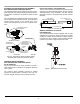
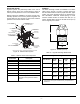
Note: Flanged restrictor for large system requirements.
Only the orifice plate is provided.
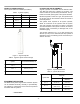
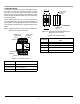
Figure 12. Flow Restrictor
Table 7. Flow Restrictor Sizes
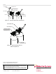
Figure 13. Restrictor Female NPT/Female NPT,
Sizes 1/2-inch to 2 inches
Table 8. Flow Restrictor Data
Part Number Description
38-250001-xxx 2-1/2 in. Flow Restrictor
38-300001-xxx 3 in. Flow Restrictor
38-400001-xxx 4 in. Flow Restrictor
FLOW
BOLT*
CLASS 1500#
FLANGE*
NUT*
GASKET*
ORIFICE PLATE
RESTRICTOR
* PROVIDED BY
INSTALLER
Part Number
Flow Restrictor FNPT x FNPT Pipe Diameter
(NPT)
38-050003-xxx 1/2 in. (13 mm) Brass, Code 035 to 075
38-100003-xxx 1 in. (25 mm) Brass, Code 050 to 130
38-150003-xxx 1-1/2 in. (38 mm) Brass, Code 085 to 220
38-200003-xxx 2 in. (51 mm) Stainless Steel, Code 115 to 270
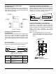
STAMPED WITH
ORIFICE DIA.
STAMPED WITH
PART NUMBER
CONNECTION FOR
DISTRIBUTION
PIPE WORK
NPT
NPT
38-XX0003-XXX