
User's Manual


- 7 -
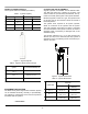
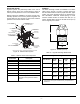
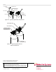
SELECTOR VALVES
Argonite systems are particularly suited to the use of
selector valves, where one central storage of agent is
used to provide protection to two or more hazard areas.
Selector valves are available in six sizes, and are pneu-
matically operated. One common pressure regulator and
vented elbow are also required to reduce the actuation
pressure to each set of selector valves.
Figure 14. Selector Valve System
Table 9. Selector Valves and Components
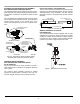
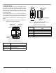
NOZZLES
The brass discharge nozzles are available in four basic
sizes 1/2-inch, 3/4-inch, 1-inch and 1-1/2-inch. Each is fit-
ted with a drilled orifice to assure proper flow rates, agent
quality and proper discharge timing as determined by
flow calculations. Maximum nozzle spacing for room
mounted nozzles should not exceed 18.8 feet (5.7 m)
square. Nozzle height should not exceed 16 feet (4.9 m)
from a single layer of nozzles.
Figure 15. Nozzles (37 mm)
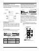
Table 10. Argonite Discharge Nozzle Data
Part Number Description
38-609800-001 1/2 in. (13 mm) Pipe Diameter
38-609800-002 3/4 in. (19 mm) Pipe Diameter
38-609800-003 1 in. (25 mm) Pipe Diameter
38-609800-004 1-1/4 in. (32 mm) Pipe Diameter
38-609800-005 1-1/2 in. (38 mm) Pipe Diameter
38-609800-006 2 in. (52 mm) Pipe Diameter
38-509803-001 Pressure regulator kit with relief
120 PSI (8.3 bar) preset for selector
valves
REDUCING BUSHING*
PRESSURE RELIEF DEVICE,
P/N 38-509836-001
SELECTOR VALVE,
1/2” TO 2” NPT
RESTRICTOR
1/2” TO 2” NPT
OUTLET FROM
RESTRICTOR TO
HAZARD #2
OUTLET FROM
RESTRICTOR TO
HAZARD #1
*NOTE: ALL FITTINGS, NIPPLES AND HOSES ARE PROVIDED BY INSTALLER
HANDLE FOR
MANUAL OPERATION
CYLINDER MANIFOLD
OUTLET
FITTING TYPICAL
3000# MIN.
NIPPLE TYPICAL
SCH. 160 MIN.
REDUCING BUSHING*
PRESSURE REGULATOR
WITH VENTED ELBOW,
P/N 38-509803-001
ACTUATION HOSE
TYPICAL,
120 PSI (8 BAR)
NORMAL WORKING PRESSURE*
Argonite Discharge Nozzle
Part Number
Size (R)
NPT
Orifice
Dia.
1
Height
(H)
Width
(W)
38-300502-xxx 1/2 in.
(13 mm)
3 to
10 mm
1-9/16 in.
(40 mm)
7/8 in.
(22 mm)
38-300752-xxx 3/4 in.
(19 mm)
7 to
14 mm
1-7/8 in.
(48 mm)
1-1/8 in.
(29 mm)
38-301002-xxx 1 in.
(25 mm)
10 to
18 mm
2-3/8 in.
(60 mm)
1-7/16 in.
(37 mm)
38-301502-xxx 1-1/2 in.
(38 mm)
15 to
26 mm
3-3/16 in.
(81 mm)
2 in.
(51 mm)
1
An orifice plate within the nozzle is custom drilled to the specific
requirements of the project as determined by computerized flow
calculations.
H
R
W