
Owner's manual


GROUND FAULT PROTECTION
National electrical codes require ground-fault equipment
protection on each heating cable branch circuit. To reduce
the risk of fire caused by damage or improper installation,
circuit breakers with a 30-mA trip level are required.
Alternative designs providing comparable levels of ground-
fault protection may also be acceptable.
HEATING CABLE TESTING AND MAINTENANCE
1.Make sure that gutter and downspouts are free of leaves
and other debris annually prior to the winter season.
2. Using a 2500-Vdc megohmmeter, check the resistance
between both of the power prongs on the plug and the
ground prong after installing the heating cable. Minimum
reading should be 1000 megohms.
3. Record the original values for each circuit, and compare
subsequent readings taken during regular maintenance
to the original values.
4. If the readings fall below 1000 megohms, replace the
cable with a new unit. Do not attempt to repair the cable.
5. Caution:·Maintenance and repair of the heating cable
system should only be preformed by a qualified electrician..
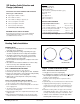
Figure 9: Downspout Termination
WARNING
Fire and shock hazard. Damaged heating cable can
cause electrical shock, arcing, and fire. Do not attempt
to repair or energize damaged heating cable. If
damaged, immediately repair or it and replace with a
new cable.
STEP 5: TERMINATING DOWNSPOUTS
1. The preferred method of installation is to run the heating
cable into the downspouts, ending the cable in a loop at
the bottom of the downspout and then run the cable
back up the downspout into the gutter . This way there is
no end seal in the downspout. For single cable runs in
downspouts with an end seal use a tie wrap to fasten it
as shown in Figure 9. Do not leave the end of the
heating cable pointing down at the end of the
downspout, double back as shown. Never create a
situation where an end seal is positioned to be a drip
point at the end of a cable run.
STEP 6: INSTALL END SEALS, SPLICES, TEES, AND
POWER CONNECTION KITS
1. If installing a GFEP device on the cable the carefully follow
the SRK08 installation instructions.
2. Use only listed weatherproof junction boxes approved for
wet location when installing SR cable.
3. ·Use only listed watertight construction or enclosures,
Type 3, 3s 4, 4X ,6,or 6P.
4. ·When possible, all power connection boxes should be
located in a protected area (such as under eaves) and
entry should be at the bottom of the box. In all case, a drip
loop should be installed, do not let an end seal or splice or
tee connection become a drip point.
STEP 7: ATTACH THE WARNING LABLES
1. Two warning labels are provided with the SR cable kit to
indicate the presence of electric deicing and snow-melting
equipment on the premises. One label should be attached
at the electrical outlet cover and the other label must be
posted at the fuse or circuit breaker panel feeding the
outlet circuit. Labels must be clearly visible.
STEP 8: CHECK AND INSPECT THE INSTALLATION
1. Prior to powering the deicing cable into the outlet, check
the entire length of the cable for mechanical damage such
as nicks and cuts in the outer insulation and any potential
thermal damaged which may have occurred if cable was
exposed to excessive heat.
2. Use a megohmmeter to test each circuit according to the
instructions in the “Heating Cable Testing and
Maintenance” section of these instructions.
3. Junction boxes should be inspected for water and for
evidence of water damage. If moisture is present, the box
should be restored to a dry condition and the cause of the
water intrusion should be investigated and eliminated.
4. Test the ground fault circuit to be sure it is functioning
properly. If malfunctioning, replace prior to energizing the
system. Functionality of over-current protection devices
such as circuit breakers or fuses should be checked as
well.
www.king-electric.com 10
Rev 11.04.12
www.king-
electric.com
10