
Owner's manual


PREPARE FOR INSTALLATION
1. Store the heating cable in a clean, dry place.
2. Inspect for any mechanical damage prior to installation.
3. Warranty is void if non-King accessories are used. King
approved accessories include:
- SRK00 Power connection kit
- SRK03 Fiberglass tape and labels
- SRK08 GFEP plug-in connection kit
- SRK10 Splice and tee kit
- SRK12 End seal kit
-SRK13 Roof clips
- SRK15 Downspout hanger bracket
4. Gutters and downspouts must be free of leaves and other
debris.
5. Carefully plan the routing of the heating cable for roof and
gutter deicing.
6. Inspected the mounting surface for sharp edges and remove
as anything that could damage the cable.
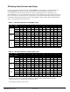
Figure 3: Shake and Shingle Roof Attachment
Figure 4: Metal Roof Attachment
Eave
overhang
Tracing
width
Tracing
height
Cable/roof
edge
None 24” 18” 2.0 ft
12” 24” 18” 2.8 ft
24” 24” 30” 3.8 ft
36” 24” 42” 4.8 ft
Eave
overhang
Tracing
width
Tracing
height
Cable/roof
edge
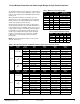
None 18” 18” 2.5 ft
12” 18” 24” 2.8 ft
24” 18” 36” 3.6 ft
36” 18” 48” 4.3 ft
None 24” 18” 2.0 ft
12” 24” 24” 2.4 ft
24” 24” 36” 2.9 ft
36” 24” 48” 3.6 ft
Heating Cable Installation
Table 7: Tracing Heights for Shake and Shingle Roof
Table 8:Tracing Heights for Metal Seam Roof
The last column gives the amount of cable required per foot of
roof edge for standard shake and shingle roof (table 7) or a
metal seam roof (table 8).
·
STEP1: CUT THE HEATING CABLE TO LENGTH
1. Cut the heating cable to length required. This can be done
before or after it is installed. Leave a minimum of 1 foot extra
heating cable for power connection. For splice connections
leave a minimum of 2 ft, and 3 ft for each tee connection.
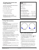
STEP 2: ATTACH THE HEATING CABLE ON ROOFS
1. Loosely loop the heating cable on the roof at the overhang
area. Pull the bottom of each heating cable loop over the roof
edge and, using a UV-resistant cable tie as. Connect the
bottom of each loop to the cable running in the gutter. This will
ensure a drainage channel for the melting ice to drain off the
roof and into the gutter and downspout. The cable in the gutter
should remain against the bottom of the gutter as shown in
Figure 3 (Standard Roof) and Figure 4 (Metal Roof).
2. Extend the top of each heating cable loop beyond where the
wall joins the roof.
3. Use SRK13 roof clips to route heating cable up and down the
edge of the roof according to the tracing height noted in the
tables above and shown in Figures 6 and 7. Route the heating
cable in such a way as to prevent abrasion to the cable jacket.
Rev 11.04.12
www.king-electric.com 8