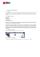
CHP 1 Pyrheliometer Instruction Manual
IMPORTANT USER INFORMATION Reading this entire manual is recommended for full understanding of the use of this product. Should you have any comments on this manual we will be pleased to receive them at: Kipp & Zonen B.V. Delftechpark 36, 2628 XH Delft, the Netherlands or P.O. Box 507, 2600 AM Delft, the Netherlands T: +31 (0)15 2755 210 F: +31 (0)15 2620 351 info@kippzonen.com www.kippzonen.com Kipp & Zonen reserves the right to make changes to the specifications without prior notice.
DECLARATION OF CONFORMITY According to EC guideline 89/336/EEC We Kipp & Zonen B.V.
TABLE OF CONTENTS IMPORTANT USER INFORMATION........................................................................................................................................ 2 WARRANTY AND LIABILITY..................................................................................................................................................... 2 DECLARATION OF CONFORMITY .................................................................................................................................
INTRODUCTION Dear customer, thank you for purchasing a Kipp & Zonen instrument. Please read this manual and the separate instruction sheet for a full understanding of the use of your pyrheliometer. The pyrheliometer CHP 1 is designed to measure the irradiance which results from the radiant flux from a solid angle of 5 °.
1 1.1 INSTALLATION AND OPERATION Delivery Check the contents of the shipment for completeness (see below) and note whether any damage has occurred during transport. If there is damage, a claim should be filed with the carrier immediately. In this case, or if the contents are incomplete, your dealer should be notified in order to facilitate the repair or replacement of the instrument. 1.
1.4 Electrical installation As standard the CHP 1 is supplied with a waterproof connector pre-wired to 10 m cable with a number of leads and a shield covered with a black sleeve. The number of connector pins and cable leads depends upon the model of pyrheliometer and whether a temperature sensor is fitted (and which type). The colour code of the wires and the connector pin numbers are shown on the instruction sheet. Longer cables are available as options.
2 2.1 OPERATION Measurement of direct solar radiation After completing the installation the pyrheliometer will be ready for operation. The irradiance value (E↓Solar) can be simply calculated by dividing the output signal (Uemf) of the pyrheliometer by its sensitivity (Sensitivity) as shown in Equation 1.
3 MAINTENANCE Once installed the pyrheliometer needs little maintenance. The window must be cleaned and inspected regularly, ideally every morning. A periodic check is to ensure that the silica gel desiccant is still coloured orange. When the yellow silica gel in the drying cartridge is turned completely transparent (normally after several months), it must be replaced by fresh silica gel as supplied in the small refill packs. The content of one pack is sufficient for one complete refill.
4 PRINCIPLE COMPONENTS OF PYRHELIOMETERS The detector of the Kipp & Zonen CHP 1 pyrheliometer is based on a passive thermal sensing element called a thermopile. The thermopile responds to the total power absorbed by the black surface coating, which is a non-spectrally selective paint, and warm up. The heat generated flows through a thermal resistance to the heat-sink (the pyrheliometer body).
5 PYRHELIOMETER PHYSICAL PROPERTIES In this chapter the principal physical characteristics of the CHP 1 pyrheliometer are given. 5.1 Spectral range The spectrum of the solar radiation reaching the Earth’s surface is in the wavelength range between 280 nm and 4000 nm, extending from ultraviolet (UV) to the far infrared (FIR) as shown in Figure 9.
5.6 Field of view Figure 4 shows the pyrheliometers optical construction. Figure 4: Optical construction The beam of light that reaches the detector is limited by the field and aperture stop. The slope, opening and limit angles are determined by R, r and L. The distance x is negligible. For the CHP 1 the full opening angle is 5 °, the slope angle is 1 °. The sun, as seen from the detector, occupies a solid angle of 0.5 °.
6 MEASUREMENT ACCURACY When a pyrheliometer is in operation, its performance is correlated to a number of parameters, such as temperature, level of irradiance etc. Normally, the supplied sensitivity figure is used to calculate the irradiances. If the conditions differ significantly from calibration conditions, uncertainty in the calculated irradiances must be expected. For a first class pyrheliometer the WMO expects maximum errors in the hourly radiation totals of 3 %.
6.4 Non-stability This is the percentage change in sensitivity over a period of one year. This effect is mostly due to degradation by UV radiation of the black absorber paint on the sensing element surface. Kipp & Zonen recommends recalibration every two years. However, for quality assurance purposes some institutes, companies or networks may require more or less frequent recalibration. Please read the chapter on the calibration procedure for pyrheliometers for more information. 6.
7 7.1 CALIBRATION Calibration principle An ideal pyrheliometer gives voltage output that is proportional to the absolute irradiance level. This relationship can be expressed as a constant ratio called ‘sensitivity’ (Sensitivity). The sensitivity figure of a particular pyrheliometer is unique. It is determined in the manufacturer's laboratory by comparison against a reference pyrheliometer of similar type.
8 RECALIBRATION Radiometer sensitivity changes with time and with exposure to radiation. Periodic calibration every two years is advised. Accurate calibrations can be done outdoors under clear conditions by comparison with a reference pyrheliometer. Many national or regional weather services have calibration facilities. Their standard pyrheliometer is compared with the World Radiometric Reference at Davos, Switzerland. This embodies several absolute cavity (black body) pyrheliometers.
APPENDIX I RADIOMETRIC TERMINOLOGY Term Explanation Albedo The portion of incoming radiation which is reflected by a surface Azimuth angle Angle in horizontal direction (0-360 °) Angle of incidence Incident angle from zenith (vertical) Cosine response Detector response according to the cosine law Diffuse solar irradiance Solar radiation, scattered by water vapor, dust and other particles as it passes through the atmosphere Direct solar irradiance Radiation that has traveled a straight path from
APPENDIX II 10K THERMISTOR SPECIFICATIONS YSI Thermistor 44031 - Resistance versus Temperature in °C T= T [”C] = Temperature R = Resistance YSI 44031 Temperature vs. Resistance Temperature [˚C] [˚F] Resistance [Ohm] Temperature [˚C] [˚F] Resistance [Ohm] Temperature [˚C] [˚F] Resistance [Ohm] -30 -22.0 135,200 0 32.0 29,490 -29 -28 -27 -20.2 -18.4 -16.6 127,900 121,100 114,600 1 33.8 30 31 86.0 87.8 8,194 7,880 89.6 108,600 102,900 97,490 -9.4 -7.6 -5.8 92,430 87,660 83,160 41.
APPENDIX III PT-100 SPECIFICATIONS Pt-100 - Resistance versus Temperature in ºC and ºF -R +1 100 T= T [”C] = Temperature R = Resistance Pt-100 Temperature vs. Resistance Temperature [˚C] [˚F] Resistance [Ohm] Temperature [˚C] [˚F] Resistance [Ohm] Temperature [˚C] [˚F] Resistance [Ohm] -30 -29 -28 -27 -26 -25 -24 -23 -22 -21 -20 -19 -18 -17 -16 -15 -14 -13 -12 -11 -10 -9 -8 -7 -6 -5 -4 -3 -2 -1 88.2 88.6 89.0 89.4 89.8 90.2 90.6 91.0 91.4 91.8 92.2 92.6 93.0 93.3 93.7 94.1 94.5 94.9 95.3 95.
APPENDIX IV MAIN SPECIFICATIONS ISO classification First Class Response time (95 %) Zero offsets due to temperature change (5 K/hr) Non-stability (change/year) Non-linearity (0 to 1000 W/m²) Temperature dependence of sensitivity Sensitivity Impedance Operating temperature Spectral range (50 % points) Typical signal output for atmospheric applications Maximum irradiance Expected daily uncertainty Full opening view angle Slope angle Required tracking accuracy Weight (excluding cable) 0.
APPENDIX V LIST OF WORLD AND REGIONAL RADIATION CENTRES World Radiation Centres Davos (Switzerland) St. Petersburg (Russia) (data centre only) Region I (Africa) - Cairo (Egypt) - Khartoum (Sudan) - Kinshasa (Dem. Rep.
APPENDIX VI RECALIBRATION SERVICE Pyrheliometers, Albedometers, Pyrgeometers, UV-Radiometers & Sunshine Duration Sensors Kipp & Zonen solar radiation measurement instruments comply with the most demanding international standards. In order to maintain the specified performance of these instruments, Kipp & Zonen recommends calibration of their instruments every two years. This can be done at the Kipp & Zonen factory. Here, recalibration to the highest standards can be performed at low cost.
Our customer support remains at your disposal for any maintenance or repair, calibration, supplies and spares. Für Servicearbeiten und Kalibrierung, Verbrauchsmaterial und Ersatzteile steht Ihnen unsere Customer Support Abteilung zur Verfügung. Notre service 'Support Clientèle' reste à votre entière disposition pour tout problème de maintenance, réparation ou d'étalonnage ainsi que pour les accessoires et pièces de rechange.