Instruction Manual CVF4 Ventilation Unit
Instruction Manual - CVF4 2
Important User Information Dear customer, thank you for purchasing a Kipp & Zonen product. It is essential that you read this manual completely for a full understanding of the proper and safe installation, use, maintenance and operation of your new CVF4 Ventilation Unit. We understand that no instruction manual is perfect, so should you have any comments regarding this manual we will be pleased to receive them at: Kipp & Zonen B.V. Delftechpark 36, 2628 XH Delft, - or P.O.
Instruction Manual - CVF4 4
Declaration of Conformity . We Kipp & Zonen B.V. Delftechpark 36, 2628 XH Delft P.O.
Instruction Manual - CVF4 6
Table of Contents .. . Important User Information ........................................................................................................................................................................................ 3 Declaration of Conformity ............................................................................................................................................................................................... 5 Table of Contents .............................
Instruction Manual - CVF4 8
1. Introduction This manual will show you how to install, use and maintain the CVF4 Ventilation Unit. The CVF4 is meant for ventilating solar radiation sensors with the purpose to keep the mounted radiometer window or dome clean from dew, precipitation and pollution. It can be used outdoors under all-weather conditions. The CVF4 has a built in heater to keep the air just above ambient temperature.
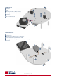
6 1.1 CVF4 top side 1 Ventilator 2 2 Heater 3 Mounting holes CMP 3, SMP3 and CGR 3 4 Mounting holes all other instruments 5 Connector 6 Cover nut 7 Slit for radiometer cable 1 3 4 4 3 2 7 5 6 1.
2. Installation The CVF4 consists of: - Base plate with ventilator, heater and connector - Replaceable filter plus cover - Top cover 2.
2.4 Installation procedure First the CVF4 is screwed flat on its mounting plate. In case the CVF4 is mounted on a solar tracker, the tracker has to be levelled first. On our sun trackers the CVF4 is positioned such that the fan sticks out over the edge of the plate. This ensures the air inlet is never blocked (see picture of the CVF4 on the SOLYS 2 Sun Tracker on the next page). The locations of the CVF4 mounting holes on the SOLYS 2 top mounting plate are shown below.
Then the radiometer is mounted in the CVF4 and levelled with its own levelling feet. Afterwards the radiometer mounting screws and shoulder washers are fitted (not secured yet). In case the CVF4 is mounted on a solar tracker, finish the alignment of the tracker first before securing the radiometer screws because tracker (and radiometer) levelling might need re-adjustment. After all mounting screws have been secured the cables of the CVF4 and the radiometer can be connected.
2.5 Electrical connections VENTILATION UNIT CONNECTION ANSCHLUSS • RACCORDEMENT • CONEXIÓN 1 Wire Function Connect with Kabel Fil Cable Funktion Fonction Función Anschluss an Relier à Conectar con Red + Ventilator Rot • Rouge • Rojo + Ventilator + Ventilateur + Ventilador +12 VDC @ 0.4 A 2 Blue + Heater Blau • Bleu • Azul + Heizung + Chauffage + Calentador +12 VDC @ 0.
3. Accessories 3.1 Spare CVF4 filters Article number 2682047 Set of 5 spare ventilation fan inlet filters. 3.2 Power supply Two optional 12 VDC power supplies are available for outdoor (CVP 1) and indoor (CVP 2) use. 3.2.1 CVP 1 Article number 0357700 The CVP 1 is a waterproof (IP 65) power supply for outdoor use with 12 VDC @ 3.5 A output. The input is wide range 100 to 240 VAC, 50 or 60 Hz. 3.2.2 CVP 2 Article number 0349401 This is a 12 VDC, 2.
3.3 CMF4 Mounting Fixture Article number 0362703 CMF4 The CMF4 consists of a mounting plate plus rod. It can be used for one CVF4, looking up or 2 CVF4’s where one is looking down. This allows for highly accurate albedo or net-radiation measurements with 2 ventilated radiometers. 3.4 CMB 1 Mounting Bracket Article number 0369701 To mount the CMF4 to a mast or wall the CMB 1 mounting bracket can be used.
3.5 Adapter for use of the CVF4 in the CM 121C shadow ring CVF4 Remove CVF4 feet (4x) and remount two feet in these counterbore holes CVF Adapter M6 x 10 cap screw (2x) Relocation of 2 of the CVF4 mounting feet to fit it on the CM 121C shadow ring The blue adapter part is included with the CM 121C.
Instruction Manual - CVF4 18
4. Maintenance Regular inspection of the CVF4 is advised. Depending on the location (air pollution) this can be monthly or yearly. When on site for inspection of other instruments it is advised to check the CVF4 filter. At the same time radiometer levelling and desiccant can be checked. For access to the desiccant the 2 mounting nuts have to be loosened and the top cover taken off. When replacing the cover, make sure it is placed correctly.
Instruction Manual - CVF4 20
5. Specification Kipp & Zonen reserves the right to make changes to specifications and other product documentation without prior notice. 5.
Instruction Manual - CVF4 22
6.
Instruction Manual - CVF4 24
7. Customer support If you require any support for your Kipp & Zonen product please contact your local representative in the first instance. The information can be found in the ‘Contact’ section of our website at www.kippzonen.com . Alternatively, you can contact us directly at www.kippzonen.
Our customer support remains at your disposal for any maintenance or repair, calibration, supplies and spares. Für Servicearbeiten und Kalibrierung, Verbrauchsmaterial und Ersatzteile steht Ihnen unsere Customer Support Abteilung zur Verfügung. Notre service 'Support Clientèle' reste à votre entière disposition pour tout problème de maintenance, réparation ou d'étalonnage ainsi que pour les accessoires et pièces de rechange.