SOLYS 2 2-Axis Sun Tracker Instruction Manual
IMPORTANT USER INFORMATION Reading this entire manual is essential for full understanding of the proper use and safe operation of this product Should you have any comments on this manual we will be pleased to receive them at: Kipp & Zonen B.V. Delftechpark 36, 2628 XH, Delft, the Netherlands P.O. Box 507, 2600 AM, Delft, the Netherlands Phone +31 (0)15 2755210 Fax +31 (0)15 2620351 Email info@kippzonen.com Web www.kippzonen.
Throughout the manual and on the SOLYS 2 instrument symbols are used to indicate to the user important information. The meaning of the symbols located on the SOLYS 2 is as follows: Caution (refer to accompanying documents) Caution, risk of electric shock Protective conductor terminal DC (Direct Current) AC (Alternating Current) The meaning of the symbols located inside the SOLYS manual 2 is as follows: Important, indicating a point of consideration.
EC TYPE DECLARATION OF CONFORMITY We: Kipp & Zonen B.V.
TABLE OF CONTENTS IMPORTANT USER INFORMATION ..............................................................................................................................1 EC Type DECLARATION OF CONFORMITY ..................................................................................................................3 TABLE OF CONTENTS ................................................................................................................................................4 1 GENERAL INFORMATION ...
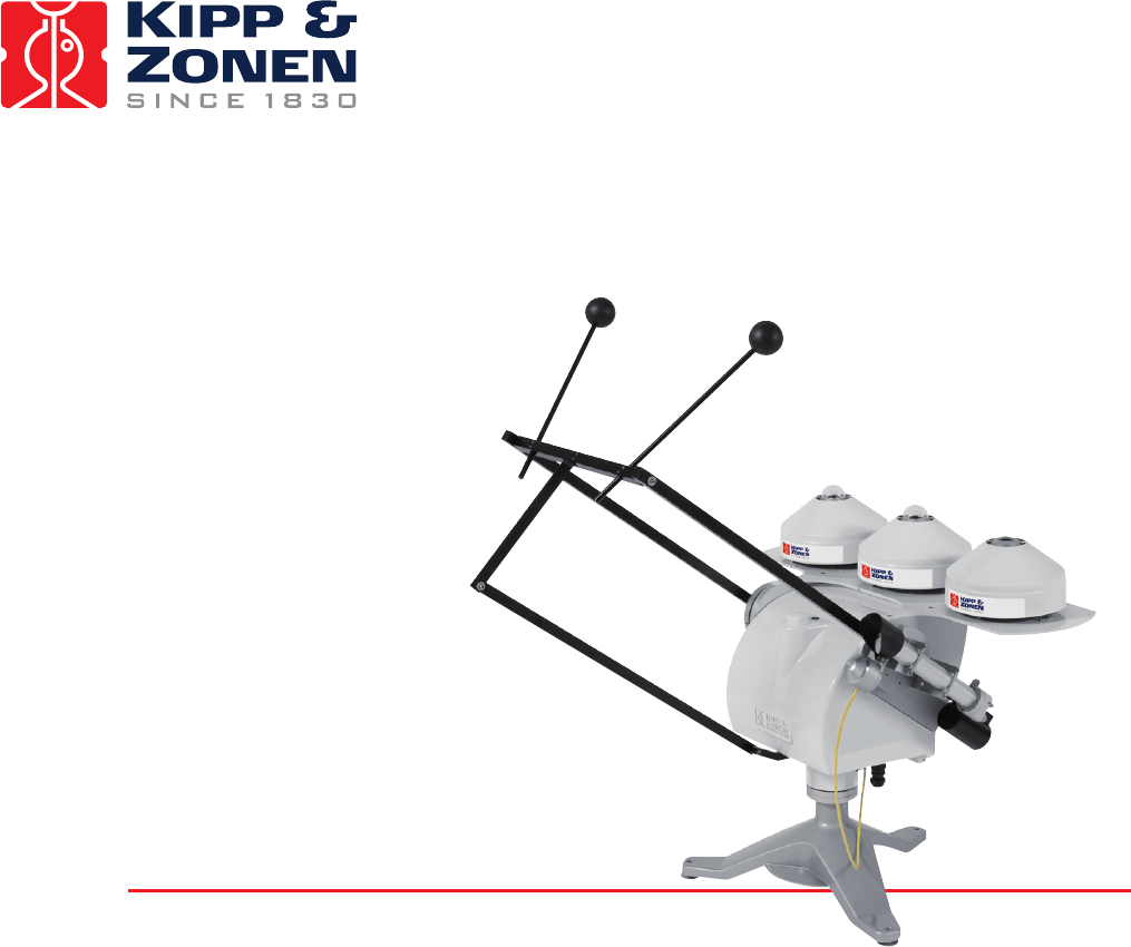
1 GENERAL INFORMATION 1.1 INTRODUCTION TO THE SOLYS 2 The SOLYS 2 two-axis sun tracker is an all-weather positioning platform used to point specialized instruments at the sun’s movement across the sky. It is fully automatic and does not require a computer or software for installation. The integrated GPS receiver automatically configures location and time data. Multi-colour LEDs indicate the operating status and an Ethernet port allows for software upgrades.
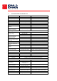
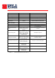
2 SPECIFICATIONS OF THE SOLYS 2 SOLYS 2 Comments Pointing accuracy < 0.1 º Meets BSRN requires requirements Torque 20 Nm Payload 20 kg Angular velocity 5 º/s Performance Angular acceleration Balanced 3.
required Functional self test Standard Multi-color LED status indicator Test / diagnostic facility Standard Via Ethernet port Sun tracking mode Standard Michalsky algorithm (1988) Flash memory Via Ethernet port No scheduled maintenance required Annual inspection recommended Firmware update possible Maintenance Automatic restart after power interruption Yes Options Sun sensor kit For active sun tracking Second side mounting plate Top mounting plate Shading ball assembly Radiometer mountin
3 INSTALLATION The following sections provide information on the installation of the SOLYS 2. The installation consists of the following steps which will be explained step by step in the sub chapters: 3.1 Required tools for SOLYS 2 mounting 3.1.1 Required tools for Shading Ball Assembly / sun sensor 3.2 Minimum operating area / considerations 3.3 Create a firm base to mount the tripod stand with the K&Z logo pointing East 3.
3.1 REQUIRED TOOLS FOR SOLYS 2 MOUNTING For installation on site the following materials are supplied with the SOLYS 2 Allen Wrench key type 6 (for M8 bolts for tripod) Allen Wrench key type 3 Allen Wrench key type 2.5 Screws M8 x 20 plus M8 washers Required but not supplied are: Screwdriver for connection of power cable to the connector Cable for power connection of the SOLYS 2 Compass to find geographical East. 3.1.
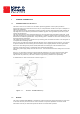
3.2 MINIMUM OPERATING AREA / CONSIDERATIONS SOLYS 2, complete with all the accessories attached, requires a substantial amount of unobstructed area to operate properly. This should be kept in mind when deciding where and how the unit is going to be installed. Figure 4.1 shows the minimum operating area with respect to both the Azimuth and Zenith axis of a SOLYS 2 complete with all accessories including Tripod Stand and Shading Ball Assembly.
3.3 CREATE A FIRM BASE TO MOUNT THE TRIPOD STAND WITH THE KIPP & ZONEN LOGO POINTING EAST The tripod feet have 11 mm mounting holes to fix the SOLYS 2 to a firm base. Illustration 4.4 will provide the necessary information to create a firm base.
3.4 MOUNT THE TRACKER ON THE TRIPOD WITH THE E ON THE MOUNTING FLANGE POINTING EAST The SOLYS 2 is supplied with a standard ∅ 102 mm bottom flange, which has a 3-hole M8 mounting pattern to match the Tripod Stand with leveling feet. The tripod has 3 slots for mounting the 3 M8 bolts to the bottom flange. Both the E mark on the bottom flange and the K&Z logo on the tripod must point East when the SOLYS 2 is mounted.
Figure 4.3: SOLYS 2 Bottom Flange Dimensions. Note: When different mounting bolts are used they must not protrude through the bottom flange Tip: When installed an initial Azimuth orientation due East with the help of a compass will do. When the SOLYS 2 is powered later on, exact positioning can be performed, when sun is available.
3.5 LEVEL THE SOLYS 2 USING THE INTEGRATED BUBBLE LEVEL AND TRIPOD FEET Prior to activating the SOLYS 2, it must be levelled on its mounting surface. To help accomplish this task, the SOLYS 2 is equipped with a high accuracy bubble on top of the housing. Adjust the levelling feet on the tripod stand to move the bubble into the centre of the level. The levelling feet can be easily adjusted using a 13 mm wrench. The accuracy of the SOLYS 2 is within 0.1°when the bubble is within the circle.
3.6 CONNECTING AC/DC POWER CAUTION, RISK OF ELECTRIC SHOCK, ALWAYS CONNECT A PROTECTED EARTH Important: Power supply SOLYS 2 can be operated on either 115/230 VAC or 24 VDC. In case both the AC and DC supplies are present and the AC power is within its operating range (90 – 264 VAC) the SOLYS 2 will use the AC power. If the AC power fails and DC power is present the SOLYS 2 will without interruption continue on DC power. Inside the SOLYS 2 a 4 A slow blow fuse is used for the internal heater.
3.6.1 CONNECTING AC/DC POWER CABLE This section will explain how to make and connect your power cable to power the SOLYS2. Important Rotation lap Please understand that by applying power to the SOLYS 2 it will trigger a routine initialization procedure. During this procedure it will check for GPS signal, make a 540° rotation and stops in home position for a complete minute. Therefore it’s advisable to actually apply the power while checking chapter 3.6.
Female connector (included) Hirschmann: CA 3 LD Cable connections: 1 = Brown (L) 2 = Blue (N) = Green/Yellow (Protective Earth) 6 - 9 mm 5 mm 9 - 12 mm Power cable for outdoor use (not included) Outer diameter: 6 - 12 mm No. of conductors: 3 21 mm Conductor colors: Blue, Brown, Green/Yellow Power cable for outdoor use (not included) Outer diameter: 6 - 12 mm No. of conductors: 3 Flexible wires: Conductor colors: Red, Brown, Green/Yellow Figure 3.
Male connector (included) Hirschmann: CA 3 LS Cable connections: 1 = Red (+ 24 VDC) 2 = Black (24 VDC GND) = Green/Yellow (Protective Earth) 6 - 9 mm 21 mm 5 mm 9 - 12 mm Power cable for outdoor use (not included) Outer diameter: 6 - 12 mm No. of conductors: 3 Flexible wires: Conductor colors: Red, Brown, Green/Yellow Figure 3.
3.6.2 ENVIRONMENTAL CONDITIONS Important: SOLYS 2 rear cover SOLYS 2 does not contain any user serviceable parts inside. Therefore it is advised not to open the rear cover. Doing so can defeat the internal optical sensors which may result in physical damage to the SOLYS 2 and/or any attached equipment. Such damage is not covered under warranty.
3.6.4 Enabling Power / Led STATUS After the SOLYS 2 has been levelled (3.5), the power cable is assembled (3.6) the power can be switched on. The SOLYS 2 will start its initializing mode. During this initializing mode, the SOLYS 2 will check for any hardware errors, presence of the GPS signal, and in additional it will make an orientation lap to check for any blockades and to check if the cable length of the SOLYS 2 (and possible instruments) is sufficient.
indicates an error of the heater fan. The heater is built-in but only operates on AC power. The Status LED gives information about the tracker operation. RED indicates starting up or hardware errors; Orange shows the GPS information not present or lost. Green is the normal operating mode with GPS status. The tables below show this information including combinations and blinking of the LED’s.
3.7 ALIGNMENT OF THE SOLYS 2 Important: Before starting the alignment please verify certain issues: -The M8 bolt which hold the tripod to the actually sun tracker should not be tightened (only by hand) -SOLYS 2 has to be leveled (3.5) -SOLYS 2 needs to be supplied with an power source (3.6) -The status LED has to be green to indicate it has received all GPS information. (3.6.5) -The power LED has to be green to indicate a correct temperature, fan and input voltage. (3.6.5) -Sun sensor is NOT connected.
3.8 SECURE M8 BOLTS After the SOLYS 2 is levelled, aligned, it’s time to fix the tripod feet to its firm base. Please perform a re-check of the levelling and alignment after the tripod feet is attached to its base. Tip: After the SOLYS 2 is levelled and properly secured recheck all radiometers for proper alignment and levelling.
4 ACCESSORY INSTALLATION This chapter provides all the information on the accessory installation of all possible SOLYS 2 accessories and instruments. 4.1 MOUNTING SIDE MOUNTING PLATE (FOR SHADING ASSEMBLY OR CHP 1 Tip: Use the 1 minute in home position to mount the (second) side mounting plate. (A power reboot will send the tracker to home position) The SOLYS 2 is supplied as standard with one Side Mounting Plate. This plate is factory installed in the correct position and needs no readjustment.
4.2 SIDE MOUNTING PLATE + PMOD-WRC PMO6 ABSOLUTE CAVITY PYRHELIOMETER Figure 4.20: Installation of PMOD-WRC PMO6 Absolute cavity Pyrheliometer on side mounting plate. Important: The SOLYS2 has only one side mounting plate present as default.
4.3 SIDE MOUNTING PLATE + MIDDLETON SPO2 SUN PHOTOMETER Figure 4.21 Installation of Middleton SPO2 sun photometer adapter on side mounting plate Important: The SOLYS2 has only one side mounting plate present as default.
4.4 SIDE MOUNTING PLATE + EPPLEY (A)HF ABSOLUTE CAVITY PYRHELIOMETER Figure 4.22: Installation of Eppley (A)HF absolute cavity Pyrheliometer on side mounting plate Important: The SOLYS2 has only one side mounting plate present as default.
4.5 ATTACHING PYRHELIOMETER Figure 4.17 shows how to install Kipp & Zonen Pyrheliometers on the Side Mounting Plate. Figure 4.17: Pyrheliometer Installation Diagram Important: Recheck the alignment using the two alignment target holes on the CHP 1 pyrheliometer Chapter 4.2, 4.3 and 4.4 have detailed information how to connect a Pyrheliometer from Eppley, WRC or Middleton. The CHP 1 has its own instruction sheet and manual for detailed information.
4.6 MOUNTING SUN SENSOR The optional Sun Sensor accessory consists of a four quadrant photo diode sensor fitted within a weather resistant enclosure with SOLYS 2 mounting hardware. The installation of the Sun Sensor is as follows: Figure 4.
Figure 4.24: Mounting the Sun Sensor.
Figure 4.25: Adjustment of Sun Sensor Important: length of 19 mm.
Unscrew the cap from the sun sensor connector on the underside of the SOLYS 2 and connect the sensor connector. Before inserting the cable please check if the CHP 1 is perfectly aligned and the m8 bolts are secured! When the sun sensor is connected for the first time, the tracker will reset (go to its home position) and return and starts using the sun sensor. Now its needs to be aligned. (See chapter 4.6.1) 4.6.
4.7 SHADING BALL ASSEMBLY The Shading Ball Assembly is comprised of several components which, when assembled to the SOLYS 2, provide a mechanical assembly to ensure accurate shading during normal solar tracking operations. Listed below is a recommended sequence of assembly: Install the Lower Pivot Bar on the underside of the SOLYS 2 with the designated screws, see figure 4.7 Figure 4.
• • • • • Attach both the Shading Drive Arms with the designated screws. Ensure the counter weights are facing down. Do not completely tighten the screws yet, some movement for installing the T-bar is required, see figure 4.8 Install the T-Bar (without ball rods). Install the plastic shoulder washers onto the threaded studs of the T-Bar. Insert the shoulder washers into the side arm end holes.
• Install the the Shading support Arm to the T-Bar and Shading Pivot Bar hole with the nylon washers and locking nut shown in figure 4.9 and 4.10 Only tighten the locking nut to minimize clearances, ensure free rotational movement. Figure 4.
Figure 4.10: Mounting of shading support arm lower part Important: To verify that the Shading Assembly will not interfere with any obstructions, move the shading ball assembly down and rotate the SOLYS 2 by hand over its entire mechanical range. (With power off) In a later firmware version a rotation lap is added in the firmware that will check this for you automatically after powering-up the SOLYS 2.
4.8 TOP MOUNTING PLATE ASSEMBLY Figure 4.11 indicates how to mount the top mounting plate. Figure 4.
4.9 MOUNTING KIPP RADIOMETERS WITHOUT VENTILATION UNIT Figure 4.15 indicates the mounting holes in detail for mounting up to three Kipp radiometers Figure 4.15: Kipp & Zonen radiometers mounting holes without Ventilation unit (CVF 3) Figure 4.19 Kipp & Zonen Pyranometer Installation Diagram.
4.10 MOUNTING KIPP & ZONEN RADIOMETERS WITH VENTILATION UNIT Figure 4.13 indicates the mounting holes in detail for mounting up to three Kipp ventilation units. Figure 4.13: Kipp & Zonen radiometers mounting holes with Ventilation unit (CVF 3) Figure 4.
4.11 MOUNTING EPPLEY RADIOMETERS WITH OR WITHOUT VENTILATION UNIT The next two illustrations will indicate the mounting holes required to mount an Eppley radiometer to the Top mounting plate: Figure 4.26 Mounting of ventilated Eppley instruments on the Top mounting Plate Figure 4.
4.12 SHADING BALL RODS ASSEMBLY The position of the shading balls depends on the type (height) of the sensor. Below in figure 4.16 and 4.14 two different positions are described for the CMP / CGR radiometers with and without ventilation unit. Be sure to use the right position in your situation. Figure 4.16: Shading Ball Rods for Kipp & Zonen radiometers without Ventilation unit (CVF 3) Figure 4.
Install the Shading Ball Rods by sliding them into the designated holes. See figure 4.12 for preliminary positioning of the Ball Rods in the T-Bar. Fine-tuning of the Ball Rods must be done later in the installation after the Verification of Levelling Procedure. DO NOT OVER-TIGHTEN the locking screws, it would make fine-tuning adjustments difficult later in the procedure. Figure 4.12: Mounting of shading ball rods Important: It’s important for the detector of the instrument to be fully shaded.
5 EXTRA ACCESSORIES Kipp & Zonen always anticipates in what the market needs. Here some additional accessories that need less explanation, but can ordered for your specific needs. 5.1 TILTED PYRANOMETER MOUNTING KIT TARGETING THE PV MARKET Figure 5.
5.2 SMALL TOP MOUNTING PLATE FOR INSTALLING A SINGLE KIPP & ZONEN RADIOMETER. Figure 5.
6 ETHERNET COMMUNICATION This section describes how to communicate with the SOLYS2 via Ethernet and how to download the LOG files from the SOLYS2 in case of troubles. Warning: Communication with the SOLYS2 is established via its network interface. However, the SOLYS 2 is not protected by an internal firewall and does not use password encryption. Therefore, the network connected must be secured properly, to avoid hacking of the SOLYS 2.
3. 4. The SOLYS2 can be connected to you PC directly or via a LAN. Choose one of these methods. a. Direct connection: connect the SOLYS2 to the PC with an Ethernet UTP cross-cable. Alternatively a switch may be used to connect both, using 2 straight Ethernet UTP cables. b. LAN connection: connect the SOLYS2 and the PC to the LAN using straight UTP cables. A DHCP server must be active on the LAN for the SOLYS2 to be able to obtain an IP address. Start Safari and open Bonjour from the Command Bar.
5. Click SOLYS2 in the Bonjour window and enter username user and password solys upon request. Note that in case of a direct connection, Windows needs a few minutes to assign itself an Automatic Private IP Address. If it does not, verify that Automatic Private IP Address of the TCP/IP properties of the PC’s network connection is enabled.
6. The SOLYS 2 communication screen will look like this: 7. In case of problems with the SOLYS 2 please download the following four LOG files and send them to Kipp & Zonen. From the SOLYS2 User Interface: a. Select Logging, and then select Log Files Archive. Save the file to the PC. b. Select Miscellaneous, and then select Info Collection. Save the file to the PC. c. Select Miscellaneous, and then select Configuration Archive. Save the file to the PC. d. Select Logging, and then select Sun Log (*.csv.gz.
6.1 EXTERNAL COMMANDS The following list of commands is available when connected to the SOLYS 2 More information is available in the SOLYS 2 user interface. (Web browser) -Low level command This enables to enter any command (two letters) without actually scrolling down the entire list of command to search for the correct one. This is normally used for experienced users. Behind every next command in this document we will provide the two letter command that can be entered in the low level command line.
(0= updates disabled) -Location and pressure (LL) To retrieve or set the latitude, longitude and nominal atmospheric pressure recorded for the site. -Lockout GPS position (LP) To retrieve or set enabling of updates to the configuration due to GPS position (longitude, latitude) changes. (1= updates enabled) (0= updates disabled) -Move (MO) Enables to send each motor (as quickly as possible) to its end position. -Motor Status (MS) To retrieve the status of each motor.
-Synchronize (SY) To put the SOLYS 2 in sleep mode in the current position after the last segment -Time (TI) To retrieve or set the internal time (Universal) -Tilt (TL) To retrieve or set the tilt induced latitude and longitude error of the tracker once it has been levelled -Track (TR) To schedule your own tracking orbit. -Version (VE) Just to indicate version information of the I/O board and application. -Maximum Velocity (VM) To retrieve or set the maximum operating velocity for all motors.
void AddCheckSum( unsigned char command[] ) { unsigned char checkSum = 0; unsigned char end = 0; /* calculate sum so far */ while ( command[ end ] ) { checkSum += command[ end ]; end++; } /* separate check bytes by a space */ checkSum += command[ end ] = ' '; end++; /* make all characters printable */ while ( checkSum < 130 || checksum > 223 ) { checkSum += command[ end ] = '^'; end++; } /* add printable checksum */ command[ end ] = 256 – checkSum; } After every command, a reply is returned.
7 MAINTENANCE The SOLYS 2 itself does not need any maintenance. The following things can be checked on visiting intervals: - Periodically check the condition of all cables and connectors. Check drying cartridges for mounted radiometers. Check if bubble level still within range. Check the sun sensor position. The SOLYS 2 itself does not need any re-calibration.
8 SOLVING PROBLEMS The SOLYS 2 is designed for long periods of operation with no operator maintenance. However, if a problem occurs that cannot be corrected by using the standard operating information supplied in the preceding sections of this manual, use the information in this chapter to identify and solve the problem. If the problem cannot be corrected after reviewing the information in the following section, contact Kipp & Zonen.
8.2 FAQ Q: A: I have a problem with the aligning the SOLYS Proper placement of the SOLYS 2 is important when installing it, as it requires a specific amount of free space to operate. Make sure the tripod is placed on a solid base. Keep in mind that final alignment is only possible when the sun is shining. The following 8 steps are required to align the SOLYS 2. in the previous paragraphs additional information is available for each step. 1. 2. 3. 4. 5. 6.
9 SOFTWARE OVERVIEW The software used in the SOLYS 2 contains open source components that are listed in the table below. This software is available from our website: www.kippzonen.com/suntrackers/SOLYS2/software/download The software and versions listed below were used during the production of this manual. Look on the website for the last revision of this list. Software Apache Avahi BusyBox Expat XML parser GNU C Library Version httpd-2.2.8 avahi-0.6.17 busybox-1.1.3 expat-2.0.0 glibc-2.3.
10 FIRMWARE Kipp & Zonen is always looking for implementing improvements by changing the hardware or firmware. It’s advised to check our website on a regular base for the latest version of the firmware. It can easily be upgraded using the network connection available on the SOLYS 2. We strongly advise to perform these updates even when your SOLYS 2 seems to operate correct. It can prevent any unwanted situations in the future.
To perform the firmware update select Software, then select Software Update. Press the Browse button, browse to the software update package file (.tar.gz) and select it. Press the Upload button and wait till the upload is completed. The upload is completed when the message “Reboot tracker to apply update” appears. Select Reboot. NOTE : Do not power off the SOLYS 2, it may render it unusable. The SOLYS 2 will install the software update package and resume normal operation in a few minutes.
11 DRAWING SIDE MOUNTING PLATE When optional components or instruments need to be installed on the side of the SOLYS 2, an additional side mounting plate is required. The next illustration is the mechanical drawing of the side mounting plate. This information is required to create mounting materials for optional components or instruments.
12 DRAWING LARGE TOP MOUNTING PLATE The Shading assembly is equipped with the top mounting plate. If a top mounting plate is required without shading assembly it can be ordered separately The Part number for the top mounting plate is 0367709. It might be necessary to adjust the large top mounting plate for suiting specific instruments. The next illustration is the mechanical drawing of the large top mounting plate.
13 HEIGHT SPECIFICATIONS SOLYS 2 INCLUDING INSTRUMENTS The next illustration is displaying the actual height of the instruments.
14 PARTNUMBERS SHADING ASSEMBLY The next illustration shows the part numbers for each of the separate components from the shading assembly in case a part is broken or damaged.
15 HOW TO GUIDE THE CABLES The next illustration shows the best way to guide all your cables. It’s strongly advised to have the proper cable length as indicated below, so that the SOLYS 2 can move freely throughout the entire year. As a security check, the SOLYS 2 will make a 540 degree rotation lap at initial power up.
16 MOUNTING UVS INSTRUMENT The next two illustrations are showing the location of the holes inside the top mounting plate, the setup for the shadow balls and a total view for mounting the UVS instruments on top of the SOLYS 2
Our customer support remains at your disposal for any maintenance or repair, calibration, supplies and spares. Für Servicearbeiten und Kalibrierung, Verbrauchsmaterial und Ersatzteile steht Ihnen unsere Customer Support Abteilung zur Verfügung. Notre service ‘Support Clientèle’ reste à votre entière disposition pour tout problème de maintenance, réparation ou d’étalonnage ainsi que pour les accessoires et pièces de rechange.