5019_102_00273_INSTAL_GB 30-05-2007 13:25 Pagina 1 KDDS 6010 - KDDD 6010 Assembly instructions
5019_102_00273_INSTAL_GB 30-05-2007 13:25 Pagina 2
5019_102_00273_INSTAL_GB 30-05-2007 13:25 Pagina 3 Note to the installer 4 Note to the customer 4 Parts supplied - double & single models 5 Tools needed 5 Installation preparation - double & signle models 6 Electrical information - double & single models 7 Service specifications - double models 8 The cavity - double models 9 Plumbing options - double models 10 Service specifications - single models 11 The cavity - single models 12 Plumbing options - single models 13 Installation
5019_102_00273_INSTAL_GB 30-05-2007 13:25 Pagina 4 Note to the installer 1. Read these instructions completely and carefully. 2. Installation of this R requires basic mechanical and electrical skills. 3. Be sure to leave these Instructions with the Customer. 4. At the completion of the installation, the Installer must perform Final Check List as per Section 11 of these Installation Instructions. R 5. Remove all packaging materials supplied with the R .
019_102_00273_INSTAL_GB 30-05-2007 13:25 Pagina 5 Parts supplied - double & single models DOUBLE MODELS INSTALLATION KIT Drain Hose Support (1) Clamp (1) Drain Hose Joiner (1) Installation Tabs (2) Wire Clips (2) Phillips 16mm Screws (7) Moisture Protection Tape (1) Prefinished Toe Kick (1) White prefinished toe kick kit or Black prefinished toe kick kit or Iridium prefinished toe kick kit SINGLE MODELS INSTALLATION KIT Clamp (1) Drain Hose Support (1) Wire Clip (1) Drain Hose Joiner (1) P
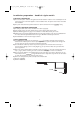
5019_102_00273_INSTAL_GB 30-05-2007 13:25 Pagina 6 Installation preparation - double & signle models ELECTRICAL PREPARATION A) The switched power outlet for the appliance should be installed in a cabinet or on a wall adjacent to the under bench space in which the appliance is to be installed. Note: The power outlet must be accessible after installation. B) The power outlet should be positioned between 150mm and 450mm from the cavity.
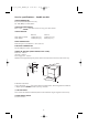
5019_102_00273_INSTAL_GB 30-05-2007 13:25 Pagina 7 Electrical information - double & single models POWER SUPPLY CORD A) Care should be taken when the appliance is installed or removed, to reduce the likelihood of damage to the power supply cord. B) If the power supply cord is damaged, it must be replaced by the Manufacturer, Service Agent or a similarly qualified person, in order to avoid a hazard. EARTHING INSTRUCTIONS A) This appliance must be earthed.
5019_102_00273_INSTAL_GB 30-05-2007 13:25 Pagina 8 Service specifications - double models WATER CONNECTION Recommended COLD (Maximum 60°C). 3/4 “ BSP (GB20) to suit flat washer. WATER SOFTENER MODELS Refer to your User Guide on how to set up your water softener. R WATER PRESSURE Maximum 1000kPa (145 p.s.i.) 1000kPa (145 p.s.i.) Water Softener Models Other Models Minimum 100kPa (14,5 p.s.i.) 30kPa (4,3 p.s.i.) DRAIN CONNECTION Drain Hose Joiner to suit Ø19mm ± 2mm waste tee.
5019_102_00273_INSTAL_GB 30-05-2007 13:25 Pagina 9 The cavity - double models Screw 14mm From front of cabinetry 100mm 109.5mm 10mm + Moisture Protection Tape 90° Ø50mm services hole immediately adjacent to corner, can be either side 50 5m 10mm moisture protection tape 822.5mm-882.5mm 645.5mm Min thickness of cavity sides is 16mm 97mm benchtop + m 580mm throughout cavity 600mm NOTE: All depth measurements are taken from the front face of the adjacent cabinetry.
5019_102_00273_INSTAL_GB 30-05-2007 13:25 Pagina 10 Plumbing options - double models OPTION 1 and Standpipe Ø38mm with Air Gap. R (750 mm - 882.5mm ) WASTE POWER OUTLET WATER SUPPLY VALVE 200mm MINIMUM BENDS RADIUS FROM VALVE WASTE OPTION 2 with Waste Disposal. Standpipe Ø38mm with Air Gap. R WASTE (750 mm - 882.5mm ) PLEASE NOTE: It is NOT recommended to connect the to any part of the Waste Disposal System.
5019_102_00273_INSTAL_GB 30-05-2007 13:25 Pagina 11 Service specifications - single models WATER CONNECTION Recommended COLD (Maximum 60°C). 3/4 “ BSP (GB20) to suit flat washer. WATER SOFTENER MODELS Refer to your User Guide on vhow to set up your water softener. R WATER PRESSURE Water Softener Models Other Models Maximum 1000kPa (145 p.s.i.) 1000kPa (145 p.s.i.) Minimum 100kPa (14,5 p.s.i.) 30kPa (4,3 p.s.i.) DRAIN CONNECTION Drain Hose Joiner to suit Ø19mm ± 2mm waste tee.
5019_102_00273_INSTAL_GB 30-05-2007 13:25 Pagina 12 The cavity - single models 100mm 10mm benchtop 90° Moisture Protection Tape 5 + 97mm 67mm + Ø50mm services hole immediately adjacent to corner, can be either side + 412mm 10mm m 05m + moisture protection tape Minimum thickness of cavity sides is 16mm 580mm throughout cavity 600mm These marks indicate mounting tab screw locations (refer to step 1 page 7) NOTE: All depth measurements are taken from the front face of the adjacent cabinetry
5019_102_00273_INSTAL_GB 30-05-2007 13:25 Pagina 13 Plumbing options - single models OPTION 1 and Standpipe Ø38mm with Air Gap. R POWER OUTLET ( 750 mm - 882.5mm ) WASTE WATER SUPPLY VALVE 200mm MINIMUM BENDS RADIUS FROM VALVE WASTE OPTION 2 with Waste Disposal. Standpipe Ø38mm with Air Gap. R POWER OUTLET ( 750 mm - 882.5mm ) WASTE PLEASE NOTE: It is NOT recommended to connect the to any part of the Waste Disposal System.
5019_102_00273_INSTAL_GB 30-05-2007 13:25 Pagina 14 Installation instructions PLEASE NOTE: Your model of may differ from the model shown in the installation diagrams. Installation is similar for all models either Single or Double. Information referring to Single models only is in italic. Installation diagrams have been simplified to enable clearer instruction. FOR INTEGRATED PRODUCTS FOLLOW THE INTEGRATED PANEL PREPARATION INSTRUCTIONS P/N 526610, BEFORE MOVING THE PRODUCT INTO THE CAVITY.
5019_102_00273_INSTAL_GB 30-05-2007 13:25 Pagina 15 Step 2: removing the tub Important! (SINGLE MODELS ONLY) The product may move. Mark chassis position on cavity. 4 6 4 SINGLE MODELS ONLY. Gently open the drawer and mark the chassis position on the cavity, before removing the tub. 5 5 Open the drawer (Bottom drawer in DOUBLE MODELS). Release the tub by depressing the right hand tub clip and pushing it back 30mm. Repeat on the left hand side. 8 6 Lift the tub up off the drawer runners.
5019_102_00273_INSTAL_GB 30-05-2007 13:25 Pagina 16 Step 3: adjusting the feet (double models only) 9 - DOUBLE MODELS ONLY Adjust the height of the product to suit the cabinetry, by turning the feet from inside the product using a wrench or M5 socket. 5mm TIP - Gently take the load off each foot using the slide and then turn by hand. NOTE: For integrated products, the upper panel may be aligned with the top of the adjacent cabinetry, provided a minimum 5mm clearance from the bench is maintained.
5019_102_00273_INSTAL_GB 30-05-2007 13:25 Pagina 17 Step 4: securing the product 10 SINGLE MODELS ONLY Check the position of the chassis is still where marked on the cavity, before securing the product. 10 11 There are four 16mm round holes, two on the left and two on the right hand side in the sound insulation. These provide access to the mounting tabs. To secure the product to the cabinetry use a 16mm Phillips screw in each mounting tab.
5019_102_00273_INSTAL_GB 30-05-2007 13:25 Pagina 18 Step 6: connecting the drain hoses 15a with Hose Joiner (see Plumbing Options). Remember to slip the wire clip(s) on the drain hose(s) first. R Attach the Drain Hose Support to the cabinetry (with the screw supplied) to prevent siphoning and to keep the drain hose(s) from kinking. If required, the Drain Hose(s) may be trimmed to a suitable length. Important! Minimum hole size to be connected to the drain system is 12.7mm.
5019_102_00273_INSTAL_GB 30-05-2007 13:25 Pagina 19 Step 7: connecting the inlet hose and power supply WARNING! DO NOT plug the product in at this stage. WENT WASTE Important! DO NOT cut the inlet hose. 18 VALVE POWER OUTLET 17 Connect the Inlet Hose to the water supply. Ensure the sealing washer is in place. The hose coupling must be tightened a further half turn after seal contact. TIP - Turn the water valve ON to check for any leaks.
5019_102_00273_INSTAL_GB 30-05-2007 13:25 Pagina 20 Step 9: trimming the toe kick (double models only) Important! Before cutting ensure the Toe Kick is positioned on a wooden chopping board to avoid damage to surrounding area. 20 20 On the chosen groove cut down the vertical ribs at the centre and the ends using a knife. Cut along full length with a knife. Turn Toe Kick over, bend and then cut from front. Sand or scrape bottom edge to remove rough patches.
5019_102_00273_INSTAL_GB 30-05-2007 13:25 Pagina 21 Step 11: Final checklist (double and single models) • Ensure product is level, securely fastened to the cabinetry and opens and closes freely. The must be free to close with no resistance from the cabinetry. • Ensure inlet hose to valve connection is tightened a further half turn after seal contact. • Ensure any knockouts or plugs in drain connection have been drilled out and drain connection has been made. • Turn ON the power and water supply.
5019_102_00273_INSTAL_GB 30-05-2007 13:25 Pagina 22
5019_102_00273_INSTAL_GB 30-05-2007 13:25 Pagina 23
5019_102_00273_INSTAL_GB Printed in Italy 05/07 5019 102 00273 30-05-2007 13:25 Pagina 24 n GB