
Installation Guide


BASE CABINET ROLL-OUT
Installation Instructions
KNAPE & VOGT MANUFACTURING COMPANY
P.O. Box 191, Muncie, IN 47308
0.899.6536 • 765.288.8730 • Fax 765.288.0851 • www.kv.com
RN-214EFS 02/03
Inspect all parts and read all instructions prior to beginning assembly and installation.
Parts Included
A. Frame sub-assembly
B. Mounting screw package
Note: Baskets sold separately
Tools Required
• Phillips screwdriver
• Drill with 1/16” bit for pilot holes
(optional)
Product Assemblies
BCO20E
BCO2456
BCO2456DM
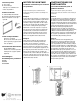
Step 1 This unit can be mounted on either side of your
cabinet. Determine which side is the most
convenient. Locate frame inside the cabinet
and align the first hole in each slide with the
cabinet front frame. Fasten with two wood
screws (sharp point). (Optional step; mark with
pencil and pre-drill holes). For system 32mm
cabinets, locate frame inside the cabinet and
align the first hole in each slide with the pre-
drilled holes. Fasten with the two euro-screws
(blunt point) provided.
Step 2 Slide frame out to expose the back
mounting holes in the slides. If
spacers are needed (not supplied),
place between the cabinet wall
and slide as shown. Fasten with
wood screws (sharp point). You
may need to use longer screws
than provided if a spacer is used.
For system 32mm cabinets, slide
frame out to expose the holes
which align with the pre-drilled
holes in the back of the cabinet.
Fasten with two euro-screws
(blunt point) provided.
A.
B.
step 1
step 2