
Installation Guide
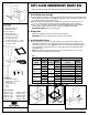


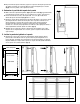

Parts Included
A. Waste Bin(s)
B. Sliding Base Assembly (1)
C. Waste Bin Chassis (1)
D. Lid(s) (if supplied)
E. Extension Brackets (2)
F. #6 x 5/8" Mounting Screws
for Door (8 = 4 + 4 extra)
G. #8 x 1" Mounting Screws
for Sliding Assembly (8 = 6 + 2 extra)
H. #10 - 24" x 1/4" Mounting Screws (4)
for Extension Brackets
SOFT-CLOSE UNDERMOUNT WASTE BIN
Inspect all parts and read all instructions prior to beginning assembly and installation.
310384-B-1014
2700 Oak Industrial Drive NE , Grand Rapids, MI 49505 USA
800.253.1561 • 616.459.3311 • www.kv.com
©2013 Knape & Vogt. All rights reserved. Made in USA. Knape & Vogt
®
reserves the right to change specifications without notice.
A
Tools Required
• Phillips head screwdriver
• Drill with 1/16" (1.5mm) bit for
drilling pilot holes
• Tape measure or ruler
• Pencil
• Scissors
• WUSC12-1-35PT
• WUSC12-1-35WH
• WUSC15-2-35PT
• WUSC15-2-35WH
• WUSC12-1-50PT
• WUSC12-1-50WH
• WUSC12-2-27PT
• WUSC12-2-27WH
• WUSC18-2-50PT
• WUSC18-2-50WH
Product Assemblies
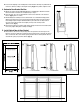
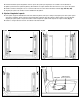
1. Install Sliding Base Assembly
A. Place sliding base assembly on cabinet floor. Align centering mark on front and rear mounting straps
with the cabinet opening. Refer to chart (Fig. 1) to determine set back. Position the front edge of the
front mounting strap at the designated set back.
B. Once the position is determined, fasten the sliding base assembly to the cabinet floor by using
4 - #8 x 1" mounting screws through the interior holes. (Fig. 2) Tighten with a screwdriver.
C. Place 2 -#8 x 1" mounting screws through the exterior holes (Fig. 3) and fasten with a Phillips
head screwdriver until the head of the screw is flush with the sliding base assembly.
DO NOT OVER TIGHTEN, as this can warp the slide.
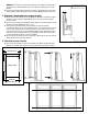
2. Remove Door
With drill or screwdriver, remove door hinges from cabinet and door.
IMPORTANT: Door must be removed prior to waste bin chassis installation.
3. Install Waste Bin Chassis
A. Lower and insert rear of chassis so that the channels on the chassis fit onto the slides on the
sliding base assembly. Push chassis toward the back of the cabinet until it sits against the back
of the slides and you hear a "click." (Fig. 5) The chassis is now fully seated and locked. Grasp the
door mount brakets, slowly pull the chassis out of the cabinet until it stops moving. Both slides
should fully extend.
NOTE: If your slides do not fully extend, your chassis is not seated properly. To correct, push
the drawer slide forward until it locks into position.
Fig. 1
OVERLAY CABINET INSET CABINET
SKU #
Cabinet
Opening Set Back
Extension
Bracket
Orientation Set Back
Extension
Bracket
Orientation
WUSC12-1-35
11.5-12
14.5-15 1.375
In
Out
1.125" + door thickness
1.375" + door thickness
Not Used
Out
WUSC12-1-50
11.5-12
14.5-15 1.375
In
Out
1.125" + door thickness
1.375" + door thickness
Not Used
Out
WUSC12-2-27
11.5-12
14.5-15 1.375
In
Out
1.125" + door thickness
1.375" + door thickness
Not Used
Out
WUSC15-2-35
14.5-15
17.5-18 1.375
In
Out
1.125" + door thickness
1.375" + door thickness
Not Used
Out
WUSC18-2-50 17.5-18 1.375 Out 1.375" + door thickness Out
Fig. 3 Fig. 5
DO NOT OVER
TIGHTEN
Fig. 2
See
Chart
D
E
B
C
G
F
H