
Datasheet


定格周囲温度 Rated Ambient Temperature :+70℃
使用温度範囲 Operating Temperature Range :−55℃〜+125℃(1F・1H)、−55℃〜+155℃(1E・1J・2A・2B・2E・W2H・W3A)
■性能 Performance
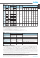
■定格 Ratings
定格電圧は 定格電力×公称抵抗値による算出値、又は表中の最高使用電圧のいずれか小さい値が定格電圧となります。
Rated voltage= Power Rating×Resistance value or Max. working voltage, whichever is lower.
※4 RK73H1F(F:±1%)及びRK73H1H(1Ω≦R≦9.1Ω、1.0MΩ≦R≦10MΩ、F:±1%)の公称抵抗値はE24となります。
※5( )内の最高使用電圧、最高過負荷電圧については、お問い合わせください。
※4 The nominal resistance value for RK73H1F(F:±1%) and RK73H1H(1Ω≦R≦9.1Ω, 1.0MΩ≦R≦10MΩ, F:±1%)is E24.
※5 Please consult with us about the Max. working voltage and the Max. overload voltage with ( ).
√ ̄ ̄ ̄ ̄ ̄ ̄ ̄ ̄ ̄ ̄ ̄ ̄
√ ̄ ̄ ̄ ̄ ̄ ̄ ̄ ̄ ̄
■使用上の注意 Precautions for Use
●
チップ抵抗器の基材はアルミナです。実装する基板との熱膨張係数の違いから、ヒートサイクル等の熱ストレスを繰り返し与えた場合、接合部のはんだ(はんだフィレット部)に
クラックが発生する場合があります。特にW2H・W3Aの大型タイプの場合、熱膨張が大きく、また、自己発熱も大きいことより、周囲温度の変動が大きく繰り返される場合や、
負荷のオンオフが繰り返される場合は、クラックの発生に注意が必要です。一般的なヒートサイクル試験をガラエポ基板(FR-4)を用い、使用温度範囲の上限・下限で行った場合、
1F〜2Eのタイプでは、クラックは発生しにくいですが、W2H・W3Aタイプは、クラックが発生しやすい傾向にあります。熱ストレスによるクラックの発生は、実装されるラン
ドの大きさ、はんだ量、実装基板の放熱性等に左右されますので、周囲温度の大きな変化や負荷のオンオフの様な使用条件が想定される場合は、十分注意して設計してください。
●
RK73H1Fでは機器組立工程における静電気の発生・印加により抵抗器が損傷する場合がありますのでご注意ください。
●
The substrate of chip resistors is alumina. Cracks may occur at the connection of solder (solder fillet portion) due to the difference of the coefficient of thermal expansion from a
mounting board when heat stress like heat cycle, etc. are repeatedly given to them. Care should be taken to the occurrence of the cracks when the change in ambient temperature or
ON /OFF of load is repeated, especially when large types of W2H/W3A which have large thermal expansion and also self heating. By general temperature cycle test using glass-
epoxy(FR-4) boards under the maximum/minimum temperatures of operating temperature range, the crack does not occur easily in the types of 1F〜2E, but the crack tends to
occur in the types of W2H/W3A. The occurrence of the crack by heat stress may be influenced by the size of a pad, solder volume, heat radiation of mounting board etc., so please
pay careful attention to designing when a big change in ambient temperature and conditions for use like ON/OFF of load can be assumed.
●
Care should be taken that RK73H1F may be damaged when static electricity occurs and is applied in the equipment.
角形面実装抵抗器
Flat Chip Resistors
本カタログに掲載の仕様は予告なく変更する場合があります。ご注文およびご使用前に納入仕様書で内容をご確認ください。 Oct.2011
車載機器、医療機器、航空機器など人命に関わったり、あるいは甚大な損害を引き起こす可能性のある機器へのご使用を検討される場合には、必ず事前にご相談ください。
Specificationsgivenhereinmaybechangedatanytimewithoutpriornotice.Pleaseconfirmtechnicalspecificationsbeforeyouorderand/oruse.
Contactoursalesrepresentativesbeforeyouuseourproductsforapplicationsincludingautomotives,medicalequipmentandaerospaceequipment.
Malfunctionorfailureoftheproductsinsuchapplicationsmaycauselossofhumanlifeorseriousdamage.
www.koanet.co.jp
形 名
Type
抵抗温度
係数
T.C.R.
(×10
−
6
/K)
定格電力
Power
Rating
抵抗値範囲
Resistance Range(Ω)
最高使用電圧
Max. Working
Voltage
最高
過負荷電圧
Max. Overload
Voltage
二次加工と包装数/リール
Packaging & Q'ty/Reel(pcs)
D:±0.5%
E24・E96
F:±1%
E24・E96
TX TBL TA TC・TCM TPL・TP TD TE
1F
±250
0.03W —
6.8k〜1M
※4
15V 30V 40,000 20,000 — — — — —
±300 10〜6.2k
※4
1H
±200
0.05W
10〜1M 10〜10M
※4
25V 50V — — 35,000
TC :10,000
TCM:15,000
— — —
±400 — 1.0〜9.1
※4
1E
±100
0.063W
10〜1M 10〜1M
50V 100V
— — — —
TPL:20,000
TP :10,000
— —
±200 —
1.0〜9.76
1.02M〜10M
1J
±100
0.1W
10〜1M 10〜1M
— — — —
TP :10,000
5,000 —
±200 —
1.0〜9.76
1.02M〜10M
2A
±100
0.125W
10〜1M 10〜1M
150V 200V — — — —
TP :10,000
5,000 4,000±200
—
1.0〜9.76
±400
1.02M〜10M
2B
±100
0.25W
10〜1M 10〜1M
200V 400V
— — — — — 5,000 4,000±200 —
1.0〜9.76
1.02M〜5.6M
±400 —
5.62M〜10M
2E
±100
0.5W 10〜1k 10〜1k
— — — — — 5,000 4,000
0.33W 1.02k〜1M 1.02k〜1M
±200
0.5W — 1.0〜9.76
0.33W
—
1.02M〜5.6M
±400 —
5.62M〜10M
W2H
±100
0.75W
10〜1M 10〜1M
— — — — — — 4,000±200 —
1.0〜9.76
1.02M〜5.6M
±400 —
5.62M〜10M
W3A
±100
1.0W
10〜1M 10〜1M
200V
(500V
※5
)
400V
(500V
※5
)
— — — — — — 4,000±200 —
1.0〜9.76
1.02M〜5.6M
±400 —
5.62M〜10M
試験項目
TestItems
規格値 PerformanceRequirements
ΔR±(%+0.05Ω)
試験方法
TestMethods
保証値 Limit 代表値 Typical
抵抗値
Resistance
規定の許容差内
Withinspecifiedtolerance
— 25℃
抵抗温度係数
T.C.R.
規定値内
WithinspecifiedT.C.R
— +25℃/−55℃and+25℃/+125℃
過負荷(短時間)
Overload(Shorttime)
2
1:1F
0.5:another
定格電圧×2.5倍を5秒印加(2Bのみ定格電圧×2倍)
Ratedvoltage×2.5for5s(2B:Ratedvoltage×2for5s)
はんだ耐熱性
Resistancetosolderingheat
1:1F〜W3A(10Ω≦R≦1MΩ)
3:1E〜W3A(R<10Ω,R>1MΩ)
0.75:1F,1H(10Ω≦R≦1MΩ)
1:1E〜W3A(R<10Ω,R>1MΩ)
0.5:another
260℃±5℃,10s±1s
温度急変
Rapidchangeoftemperature
1:1F
0.5:another
0.5:1F
0.3:another
−55℃(30min.)/+125℃(30min.)100cycles
耐湿負荷
Moistureresistance
2:1J,2A,2B
3:another
0.75:1J,2A,2B
1.5:1F
1:another
40℃±2℃,90%〜95%RH,1000h
1.5時間ON/0.5時間OFFの周期1.5hON/0.5hOFFcycle
70℃での耐久性
Enduranceat70℃
2:1J,2A,2B
3:another
0.75:1J,2A,2B
1:another
70℃±2℃,1000h
1.5時間ON/0.5時間OFFの周期1.5hON/0.5hOFFcycle
高温放置
Hightemperatureexposure
1
0.5:1F
0.3:another
+125℃,1000h:1F,1H
+155℃,1000h:1E,1J,2A,2B,2E,W2H,W3A