
Installation Guide


4
1007251-2-
B
Kohler Co.
2. Lift lavatory out of countertop with fitting and drain attached, if
applicable.
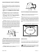
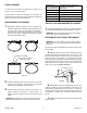
3. Refer to Fig. #6 . Cut out inside of cut-out template with
scissors on the inside line.
Fig. #6
4. Refer to Fig. #7 . Set the cut-out template on the countertop
so the backsplash locator line is touching the countertop
backsplash. The cut-out template can be moved forward from this
position to get the best placement of the lavatory on the countertop.
Tracethe cut-out opening on the countertop using a soft lead pencil.
Centerlines are provided to help align opening. Mark the final
centerline on the countertop using the cut-out template. Drill the
faucet holes using the following chart to determine their size.
NOTE: If there is not enough room at the front of the counter for
the lavatory rim, a larger countertop is needed.
Dimensions Are For Kohler Faucets Only. When Using Other
Faucets, Contact Supplier For Installation Instructions And
Dimensions.
FAUCET CENTERS VALVE HOLES SPOUT HOLE
4” (10.2cm) 1-3/16” (3cm) 1-3/16” (3cm)
6” (15.2cm)
8” (20.3cm)
12” (30.5cm)
16” (40.6cm)
1-3/8” (3.5cm) 1-3/16” (3cm)
Faucet Escutcheo n Handle Escutcheon
1/4” (6mm) Min.
Centerl ine
Fig. #7
Backsplash
Counter top
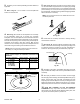
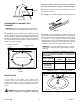
5. Refer to Fig. #8 . Drill a pilot hole into the counterto p using a
1/2” drill. Use a saber or keyhole saw to cut out opening by carefully
following the pencil line traced from cut-out template. Temporarily
position lav atory into counter, and trace a light pen cil line around
the outside edge. This will serve asa guidelinefor applying sealant.
Remove fixture from countertop.
NOTE: The rim must be traced so the sealant will cover and
conceal the pencil line.
Fig. #8
6. Install faucet to countertop and drain to lavatory following
manufacturer’s instructions.
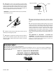
7. Refer to Fig. #9 . Apply two ribbonsof plumbersputty orother
sealant on the counter from the edge of the opening to edge of rim
as measured in Step 5 according to the putty manufacturer’ s
instructions. Quickly spread putty or sealant with a putty knife.
Plumbers Putty
Lavatory
Counter top
Fig. #9
8. Set lavatory into pos ition. Immediately wipe away any excess
putty or sealant with a damp cloth. Fill in any voids between rim and
count ertop.
9. Allow putty or sealant to set for 30 minutes. Connect supply
lines at supply valves and fitting. Assemble adjustable drain pop-up
linkage. Connect drain, trap, and outlet. Turn tailpiece into drain
body. Align trap inlet with tailpiece. Insert trap nut and gasket onto
tailpiece, and insert into trap. Tailpiece must extend 1” to2” into trap.
Tailpiece may have to be cutto fit. Turn on water and check for leaks.
10. CARE AND CLEANING. DO NOT USE ABRASIVE
CLEANSERS as they ma y scratch the sur f ace of thi s f ix tu re.
Clean up with a non-abrasive cleaner. Stubborn stains, paint, or tar
may be removed with turpentine or paint thinner.