
Instructions / Assembly


2 TT-1482 5/12
Safety Precautions
Observe the following safety precautions while installing
the kit.
Accidental starting.
Can cause severe injury or death.
Disconnect the battery cables before
working on the generator set.
Remove the negative (--) lead first
when disconnecting the battery.
Reconnect the negative (--) lead last
when reconnecting the battery.
WARNING
Disabling the generator set. Accidental starting can
cause severe injury or death. Before working on the
generator set or connected equipment, disable the generator
set as follows: (1) Move the generator set master switch to the
OFF position. (2) Disconnect the power to the battery charger.
(3) Remove the battery cables, negative (--) lead first.
Reconnect the negative (--) lead last when reconnecting the
battery. Follow these precautions to prevent starting of the
generator set by an automatic transfer switch, remote
start/stop switch, or engine start command from a remote
computer.
Hot engine and exhaust system.
Can cause severe injury or death.
Do not work on the generator set until
it cools.
WARNING
Servicing the engine heater. Hot parts can cause minor
personal injury or property damage. Install the heater
before connecting it to power. Operating the heater before
installation can cause burns and component damage.
Disconnect power to the heater and allow it to cool before
servicing the heater or nearby parts.
Installation Procedure
1. Turn off the generator set.
a. 17/18RES/RESL: Move the generator set
master switch to the OFF position.
b. 20RES/RESL: Press the OFF button on the
generator set controller and remove the F3 fuse
from the RDC/DC controller.
c. 20RESA/RESAL: Press the OFF button on the
generator set controller.
2. Disconnect the utility power to the generator set.
3. Disconnect the generator set engine starting
battery(ies), negative (--) lead first.
4. For Model 20RESA/RESAL, skip to step 8.
5. Open the enclosure roof and remove the air intake
end panel to access the air cleaner and the
receptacles below the controller.
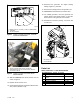
6. Remove and discard the existing plug from the
opening in the bulkhead. See Figure 3.
7. Install bushing X-634-15 (models 17/18) or
X-634-16 (model 20RES/RESL) in the opening.
No bushing is required for the Model
20RESA/RESAL.
8. For easier access to the carburetor heater location,
remove the air cleaner cover.
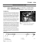
9. Disconnect the heater element from the power
cord at the plug connector. See Figure 2.
10. Insert the carburetor heater into the boss on the
engine and tighten. See Figure 1.
11. Plug in the power cord:
a. 17/18 kW and Model 20RES/RESL:Thread the
heater’s power cord through the opening in the
bulkhead. See Figure 3.
Plug the power cord into one of the receptacles
under the controller or the receptacle provided
bytheinstaller. SeeFigure3orFigure4.
b. Model 20RESA/RESAL: Plug the power cord
into the receptacle provided inside the engine
compartment. Collect the excess cable and
secure with a cable tie. See Figure 4.
12. Reconnect the power cord to the heater at the plug.