
Specification
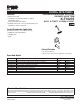

Technical Information
Required Accessories
K-304-K Rite-Temp valve without stops, NPT connections OR ❑ NA
K-304-KS Rite-Temp valve with stops, NPT connections OR ❑ NA
K-306-KS HiFlow Rite-Temp valve with stops, NPT connections OR ❑ NA
K-304-KP Rite-Temp valve with PVC connections ❑ NA
Recommended Accessories
HiFlow Rite-Temp thin wall installation kit* 88526
* Required when using the K-306-KS valve in a fiberglass
or acrylic installation.
Optional Accessories
Forté deep roughing-in kit for Rite-Temp
valve (lever handles)
1025388
Installation Notes
WARNING: Risk of damage to the K-306-KS
valve assembly. When using the K-306-KS valve
in a fiberglass or acrylic installation, use the thin
wall installation kit (88526).
Install this product according to the installation guide.
Install Rite-Temp valve according to valve installation guide.
Avoid cross-flow conditions. Do not install shut-off device on
either valve outlet.
Cap shower outlet if deck-mounted spout, diverter, or
handshower is connected to the spout outlet.
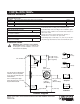
Install straight pipe or tube drop of 7″ (17.8 cm) to 18″ (45.7
cm) with single elbow between valve and wall-mount spout.
Sculpted
Sculpted
Traditional
72" (182.9 cm) –
78" (198.1 cm) to
Floor (Typical)
4" (10.2 cm)
2-7/8"
(7.3 cm)
3"
(7.6 cm)
10" (25.4 cm)
to Spout
(Bath Only)
48" (121.4 cm)
to Floor
(Shower Only)
Top of Bath
5-1/4" (13.3 cm)
5-1/4" (13.3 cm)
Traditional
5-1/4" (13.3 cm)
6"
(15.2 cm)
6"
(15.2 cm)
6-3/8"
(16.2 cm) D.
For slip-fit spout, tubing must
extend 2-1/8" (5.4 cm) Min;
3-1/2" (8.9 cm) Max beyond
finished wall.
For 1/2" NPT spout, pipe
must extend 4-1/2" (11.4 cm)
beyond finished wall.
1/2"-14 NPT
Product Diagram
FORTÉ
®
RITE-TEMP
®
FORTÉ
®
RITE-TEMP
®
PRESSURE-BALANCING BATH AND SHOWER VALVE TRIM
Page2of2
1018257-4-
G