
Specification

Technical Information
Required Accessories
K-2971-KS HiFlow Rite-Temp valve with stops ❑ NA
* For a complete listing of all the Rite-Temp valves, refer to the K-304-* Specification Sheet or Roughing-In sheet.
Optional Accessories
88526 HiFlow Rite-Temp
®
thin
wall installation kit
❑ CP ❑ Other __
1030932 Deep roughing-in kit for
Rite-Temp
®
valve (lever
handles)
❑ NA
Installation Notes
Install this product according to the installation guide.
Install the Rite-Temp
®
valve according to the valve installation
guide.
NOTICE: Risk of product damage. Long screws, for
installing trim, can damage the K-2971-KS valve. Consult the
trim installation guide to verify if the thin wall installation kit
(88526) is needed.
Avoid cross-flow conditions. Do not install shut-off device on
either valve outlet.
Cap shower outlet if deck-mounted spout, diverter, or
handshower is connected to the spout outlet.
Install straight pipe or tube drop of 7″ (17.8 cm) to 18″
(45.7 cm) with single elbow between valve and wall-mount
spout.
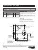
1/2" NPT
1/2" Hot
1/2" Cold
Top of Rim
4-7/16" (11.3 cm)
7" (17.8 cm) D.
5-1/2"
(14 cm)
72" (182.9 cm) - 78" (198.1 cm)
To Floor (Typical)
5-5/8"
(14.3 cm)
2-3/4" (7 cm)
Thin Wall
3-1/2" (8.9 cm)
Thick Wall
4"
(10.2 cm)
10"
(25.4 cm)
48" (121.9 cm)
To Floor
(Shower Only)
Complete Bath and Shower Faucet with Rite-Temp
Valve and Slip-Fit Diverter Spout Shown.
For Slip-Fit Spout,
5/8" OD Tubing Must Extend
1-1/2" (3.8 cm) Min; to
2-7/8" (7.3 cm) Max
Beyond the Finished Wall.
Product Diagram
DEVONSHIRE
®
RITE-TEMP
®
DEVONSHIRE
®
RITE-TEMP
®
PRESSURE-BALANCING BATH/SHOWER VALVE TRIM
Page2of2
1012741-4-
E