
Installation Guide

4. Make Electrical Connections
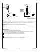
NOTE: The electrical rating of the product is printed on a label on the pump/blower end of the bath. All
baths are designed to operate between 220 V and 240 V at either 50 Hz or 60 Hz.
NOTE: The whirlpool pump control and blower motor control each come equipped with a wiring
junction box.
WARNING: Risk of electric shock. Disconnect the power before performing the following
procedures.
WARNING: Risk of electric shock. Connect the pump and blower to a properly grounded
Ground-Fault Circuit-Interrupter (GFCI) or Residual Current Device (RCD) for protection against
line-to-ground shock hazard. A single 220-240 V, 20 A, 50/60 Hz dedicated circuit is required.
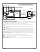
IMPORTANT! There should be no connection to the load neutral terminal on the GFCI breaker. The
green wire with the yellow stripe is the equipment ground and needs to be connected to the neutral bus
in the main circuit breaker box.
Follow local electrical codes. Bond in accordance with national and local codes.
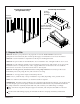
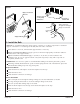
Connect electrical service to the two junction boxes. Each junction box contains three wires: blue,
brown, and green with a yellow stripe.
Ensure the equipment ground (green wire with a yellow stripe) is connected to the neutral bus in
the main breaker box.
Neutral
Bus
NL1L2
120 V
120 V
240 V
S/N
*Equipment Ground
*Line Neutral (White)
Breaker Box
Typical Two-Pole
Circuit Breaker
with GFCI
120/240 VAC Source
No Connection
(Load Neutral)
*Connections to be Made
at the Circuit Breaker
*L1
*L2
240 V
Bond in accordance with national and local codes. Open
bonding lugs are located at the top of the junction box.
Field Wiring
(From Junction
Box To GFCI Breaker)
Typical Wiring Connection for North America
Wire
Connector
Brown (L2)
Blue (L1)
From Control
Ground
(Green with
Yellow Stripe)
Electrician to
provide suitable
strain relief.
Junction
Box
1208018-2-D 8 Kohler Co.